Page 45
© 2001-2015 attocube systems AG. Product and company names listed are trademarks or trade names of their respective
companies. Any rights not expressly granted herein are reserved. ATTENTION: Specifications and technical data are subject
to change without notice.
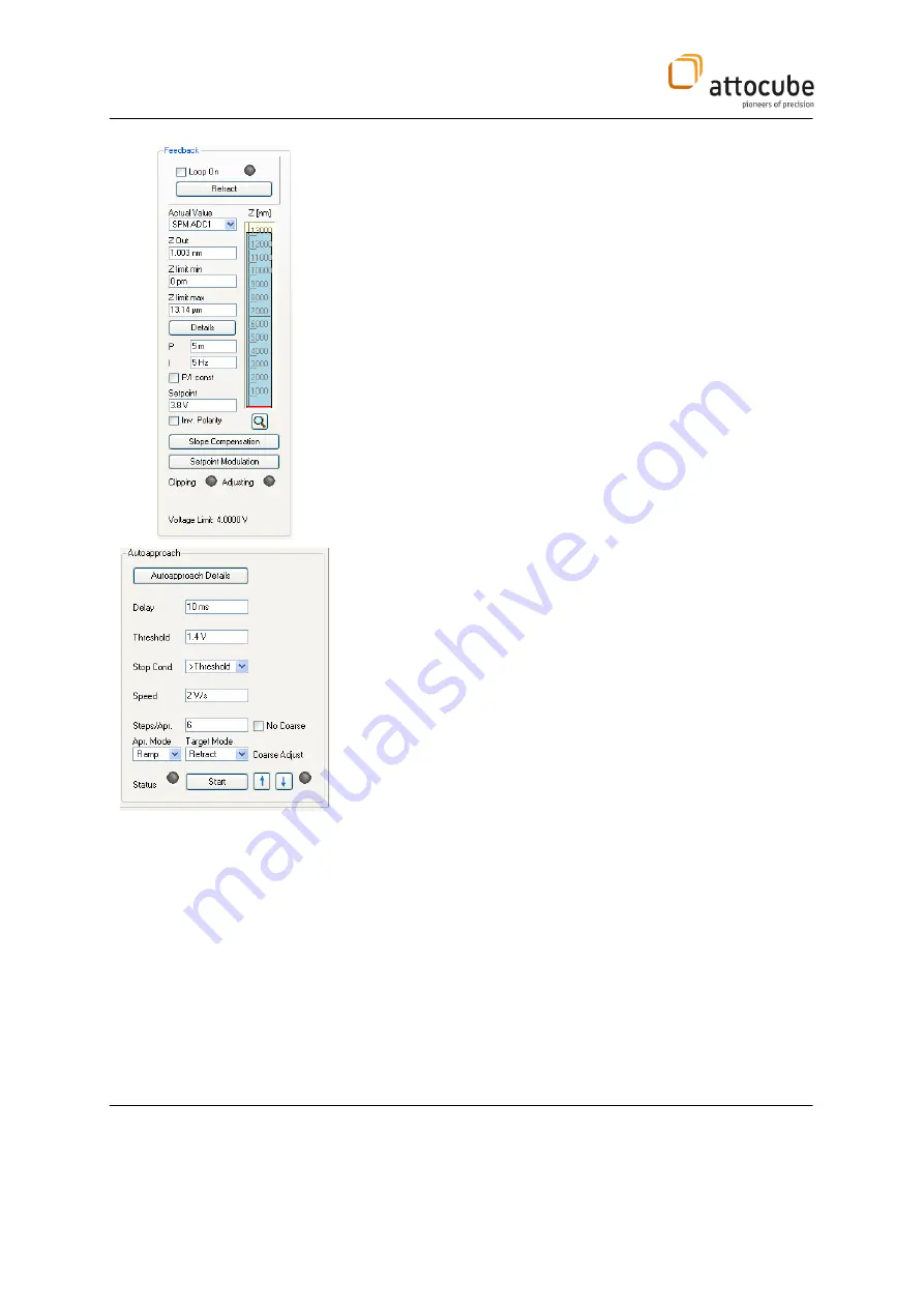
Before starting the auto approach select the ADC1 as ‘Actual Value’ in the
'Feedback' box. Furthermore choose the following parameters :
Actual Value:
SPM ADC1
Z out:
0nm
Z limit min:
0nm
Z limit max:
maximum z scanner stroke (see data sheet at the end
of the manual).
P:
1-5 m
I:
10-50 Hz
Setpoint:
Working point WP as indicated in Figure 18.
Inv. Polarity:
not checked (signal ADC1 is expected to increase with
increasing Z)
In the 'Coarse' tab one can find the 'Auto Approach' box where the
following parameters should be entered:
Delay:
10ms
Threshold:
a value bigger than ADC1
min
Stop Cond.:
> Threshold
Speed:
2V/s (@RT), 3V/s (@LT)
Steps/Apr.:
See Data Sheet at the end of this section
Apr. Mode.:
When the stop condition is met, you can either
tell the ASC 500 to remain within the feedback
mode or to immediately retract. To choose
'Retract' is of course the safer procedure.
Target Mode:
Retract


