Page 10
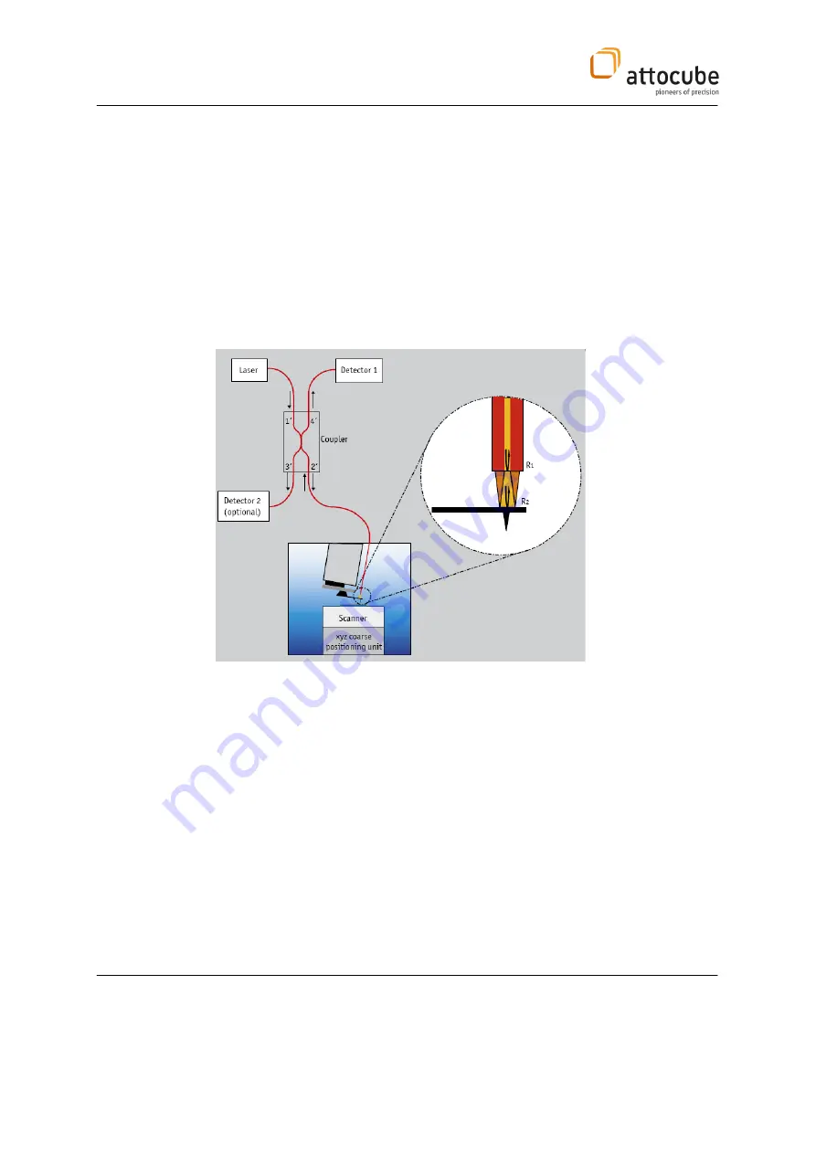
The force detection scheme for the attoAFM I microscope system is
based on an all fiber low-coherence interferometer (seeFigure 3).
Via a 50/50 fiber coupler, a laser beam illuminates a cavity built up
from the end-face of the fiber and the back-face of the cantilever. The
light reflected back from these surfaces gives rise to interferences that
can be seen by a detector. Due to the low reflectivity constants these
surfaces form a low-finesse Fabry-Perot cavity.
Monitoring the intensity of the interference fringes allows measuring
the tip deflection. The low coherence of the laser source has the
advantage of eliminating spurious interference signals resulting from
other reflections in the setup (e.g. the coupler), thus leading to an
increase of the signal-to-noise ratio of about 30 dB.
Figure 3
: Schematic drawing of the AFM I setup.
The periodicity of the signal corresponds to half the wavelength
of the
laser source.
Hence, the system can be easily calibrated and a measured
voltage difference can be translated into a height difference.
The control fiber has to be adjusted with respect to the cantilever in such a
way that the interference signal is at the quadrature point, i.e. in the
middle between two extrema values. In this case, the sensitivity of the
sensor is highest.
There are different ways to perform topographic images. Common modes
are the so-called contact- and non-contact modes.


