


11/10/2008
1000-102-930
-
INST
2
water/methanol, or any other mixture of water with combustible fluids, can
harm your vehicle's motor and the Water Boy components.
Testing done by
ATS Diesel showed that injecting water/methanol causes a dangerous spike in
cylinder pressures. You can make more
(and safer)
power by adding fuel
through more aggressive E-Power Tuning and/or ATS Injectors/Fuel Systems
than you can by using water/methanol injection. The Water Boy can control the
increased EGT that would result from adding fuel.
DO NOT USE WATER/METHANOL WITH THE ATS WATER BOY
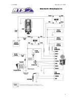
How the Water Boy Works
This kit is designed to progressively inject three stages of water. When the
system is armed with the power switch, the LED will be green. The first stage
activates when the EGT probe senses a temperature above the setting chosen
on the electronics box. A smaller "A" nozzle should be used for stage one if you
are using more than one size nozzle. When stage one is active, the LED will be
yellow. The second stage will activate when the EGT probe senses a
temperature above the setting for level two, AND approximately 10 psi of boost
or more (or 25 psi if the pink wire is not connected-See section below on Boost
Level Setting). The LED will change to Orange when Stage 2 is active (during
stage 2, the stage 1 nozzle will also be active). The third stage will activate when
the EGT probe senses a temperature above the box setting AND the boost
sensor measures approximately 15 psi (or 30-see Boost Level Setting section) of
boost or more. During stage 3, all three nozzles will be active and the LED will
be Red. When the tank is close to empty, the float switch will cut off supply power
to the pump. This will be indicated by a typical flickering of the LED. This will stop
pump “air-locking” which will help prevent the premature pump failure.
Boost Level Setting
In the Water Boy wiring harness, you will notice a purple wire. If you connect this
wire to a good ground the boost settings will be approximately 10 psi for stage 2
and 15 psi for stage 3. If this wire is not connected the boost setting will be
approximately 25 psi for stage 2 and 30 psi for stage 3. The harness is
assembled at ATS with the purple wire connected to ground. If the higher boost
levels are desired, then cut the purple wire. Choose the boost settings to suit
your vehicle’s performance. If the vehicle produces less than 35 psi of boost,
then use the lower settings.
Adjusting the Water Boy
The EGT settings at which each stage will activate can be adjusted to dial in the
Water Boy response to fit your needs and driving style. There are three small
Phillips head screws on the electronics board. Turning the screw counter-
clockwise will increase the temperature. Adjust the screws so that they will
activate progressively (stage one will be the lowest of the three temperatures).