background image

16

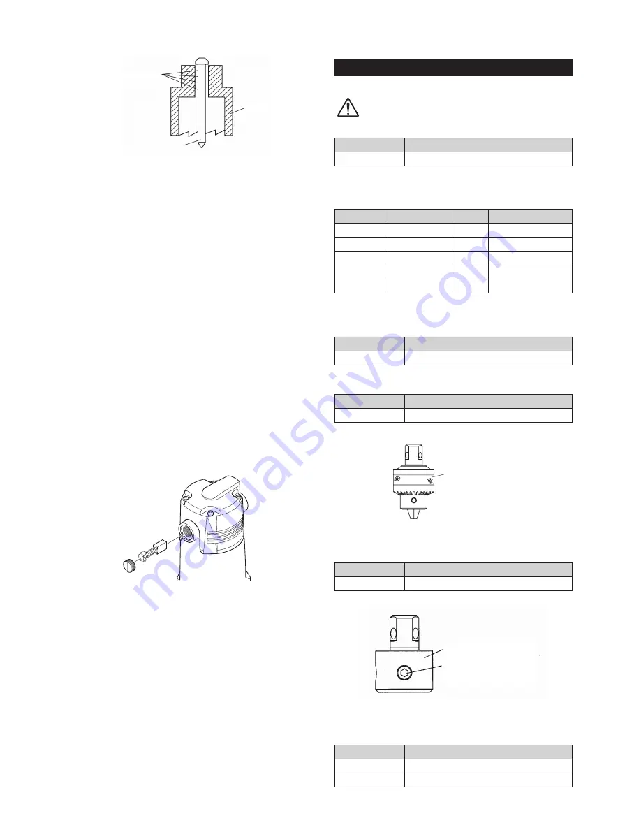
Cutting chips

Pilot Pin

Cutter

Fig. 33

9-6. Cutter Regrinding

When you need to regrind cutter, please contact 

sales agent through which you have purchased your 

machine or an authorized dealer near you.

9-7. Carbon Brushes Inspection and Replacement

Check Carbon Brushes for wear periodically.

This  machine  has  a  "switch-off  brush"  which 

automatically stops the motor to protect it when the 

carbon brushes reach the application limits.

When the brushes reach the limits, replace both 

brushes with the new ones according to the following 

procedures. (Fig.34)

Check - machine failure.

(1) Remove  the Brush Cap with a straight slot 

screwdriver.

(2) Remove the worn-out Carbon Brush and replace 

it with a new one. Then reattach the Brush Cap.

(3) After replacing the Brush, operate the unit for 

about ten minutes with no load.

Fig. 34

10  OPTIONAL PARTS

10-1. Nitto-Brand Cutting Oil

CAUTION

Use Nitto-brand Cutting Oil for Atra Ace.

Part No.

Part Name

TB01507

Cutting Oil 2

 (Light Blue)

10-2. Pilot Pin

(metric size)

Part No.

Part Name Depth (mm) Applicable (mm)

TK01167 Pilot Pin 06025

25

Jetbroach 12-17dia.

TJ15859 Pilot Pin 08035

35

Jetbroach 17.5-32dia.

TK01166 Pilot Pin 06050

50

Jetbroach 12-17dia.

TJ16019 Pilot Pin 08050

50

Jetbroach 17.5-32dia.

(TK00802) Pilot Pin 0850

50

(   ):Special Order

10-3. Supporting Magnet Ass

y

Part No.

Part Name

TB04374

Supporting Magnet Ass’y

10-4. Twist Drill Adapter 

(Fig.35)

Part No.

Part Name

TB07690

Drill Adapter Ass’y

Drill Adapter Ass’y

Fig. 35

10-5. Side-Lock Cutter Adapter 

(Fig.36)

Part No.

Part Name

TB05188

Adapter Ass’y

Adapter
Hex. Socket Set Screw

with Dog Point 10X7.5

Fig. 36

10-6. Jet Oiler 

(Fig.37)

Part No.

Part Name

TQ10581

Jet Oiler

TQ05275

Tube 4×7×1000

WOJ-3200.indd   16

10.11.12   11:14:34 PM

Summary of Contents for WOJ-3200

Page 1: ... 4 3 A No load Speed 870 min 1 Load Speed 550 min 1 Magnet Power Consumption 70 W Hole Capacity JETBROACH One touch Type Hole diameter MAX φ32 mm Plate thickness MAX 50 mm Twist Drill MAX 13 mm Magnet Holding Power 9000 N Magnet Size 99 mm 177 mm Weight 13 kg Short Circuit Current Rating 5kA The specifications and configurations contained in this document are subject to change without prior notice...

Page 2: ...wer tool if the instructions supplied are not followed Do not allow the main body or the power source to get wet as it will cause electric shock and leakage Using this tool improperly could result in serious injury Read the instruction manual before using Always wear suitable eye protection Always wear suitable hearing protection Always wear respiratory protective equipment PPE Sound Pressure Leve...

Page 3: ...tip will cause severe injuries Always keep all parts of your body away from the cutting tip Always keep your hand and clothing away from the cutting tip ABOUT THE WORK AREA Keep Work Area Clean Always keep your work area clean Cluttered work areas cause accidents Always keep clear of other objects Never use the magnetic drilling machine when it is wet Always use the drilling machine in a dry area ...

Page 4: ...Do not operate the machine with a damaged or worn pilot pin Do not operate the machine with any damaged accessory Operating the machine with any damaged part or accessory can cause accidents and severe injuries If there is any damage to the magnetic drilling machine do not operate the machine Take it to an authorized Nitto Dealer for repair Always have the magnetic drilling machine repaired at an ...

Page 5: ...you are not using the Magnet turn the switch to the OFF position and pull the Plug out of the power source Do not use the Drill Motor for over 30 minutes Uninterrupted operation of the Drill Motor for over 30 minutes generates heat This heat can cause a fire Never use the Drill Motor for over 30 minutes When you are not using the Drill Motor turn the switch to the OFF position and pull the Plug fr...

Page 6: ...chine to the work piece If you do not use the Safety strap it is possible that the machine may fall Fig 4 If use of the Safety strap is not possible because of the size of the work piece you must use another method of securing the machine Use a Supporting Magnet Assy to prevent the machine from falling The use of a Supporting Magnet Assy is shown below Fig 5 Supporting Magnet Assy Fig 4 Supporting...

Page 7: ... of an engine driven welder as a power source may cause your magnetic driven machine to malfunction Power from an engine driven welder can damage the electronic circuits in your portable drilling machine Use a Proper extension cord Do not use an extension cord that is too thin Do not use an extension cord that is too long Do not use an extension cord that is wound on a drum Do not share an extensi...

Page 8: ...kes place 2 RECEIVING INSPECTION Upon unpacking check to see that the shipment is complete without damage or oil leakage in transport Should you find any damage or short shipment please contact sales agent through which you have purchased your machine or an authorized dealer near you for corrective actions Package Contents Q ty Check ATRA ACE 1set Pilot Pin 08050 1 Hex Socket Screw Key 3 1 Spanner...

Page 9: ...ear of the machine to start the Drill Motor 4 3 Magnet Interlocking Function If the magnet is disconnected the lamp will blink in red and the Drill Motor will not revolve When the Magnet fails the Drill Motor will not start revolving To repair defective Magnet please contact sales agent through which you have purchased your machine or an authorized dealer near you 5 MACHINE SETUP WARNING When sett...

Page 10: ...al Keep Cutting Oil out of reach of children Don t drink Cutting Oil 3 First Aid If Cutting Oil gets into your eyes immediately open your eyelids with your fingers and wash your eyes with plenty of water for at least 15 minutes If your eyes feel irritated consult with a medical doctor and follow his her instructions If Cutting Oil comes into contact with your skin immediately wash it away with ple...

Page 11: ... Oil by 8 to 10 fold Do not use well water 1 3 Cutting oil should be supplied to the drill using the Jet Oiler or the Tank both of which are sold separately 5 5 Position Change of Rod Handles Rod Handles can be positioned either on the right or left side of the machine by changing the Pinion Shaft insert direction as follows 1 Unscrew Hex Soc Head Cap Screw 8x20 using Hex Socket Screw Key 6 includ...

Page 12: ...t Keep all surfaces clean of rust chips or other foreign material 3 Aligning with Punch Mark Turn the Rod Handle counterclockwise to slightly lower the cutter and align the tip of Pilot Pin to the punch mark Fig 20 Punch Mark Fig 20 4 Magnet ON WARNING Check to see that Magnetic power is at work Turn on the Magnet Switch The switch lamp will glow and magnetic power will come on 5 Mounting the Guar...

Page 13: ...ps Do not touch the slug Do not use your hands to remove chips After completion of drilling operation lift the Drill Motor and turn OFF the Motor Switch Fig 25 When the Drill Motor stops immediately turn OFF the Magnet Switch Fig 26 If the Magnet Switch is kept ON for a long time the continuous current flowing through the Magnet could shorten the service life of the Magnet MAGNET push MOTOR push F...

Page 14: ...w you can change the location of the handle freely On releasing the handle the spring causes the handle to return to its original position The handle is then locked in that position Place the drill in a location that allows it to be operated easily Fig 29 30 Lift up clamp lever Fig 29 Position is 360 changeable pull clamp lever Fig 30 2 Attaching the Adapter Attach the Adapter that is sold separat...

Page 15: ... is disconnected Request for repair Orange lamp blinks the workpiece is displaced after magnet attraction Fix the workpiece Drill Motor stops during drilling Magnet is not working with Magnet lamp not illuminating Power failure has occurred or power supply plug is disconnected After power failure is restored or power supply plug is re connected turn on Motor Switch again The rotation of Drill Moto...

Page 16: ...essive clearance between the machine body and Gearbox would deteriorate not only drilling performance but also cutting tool life to a substantial degree If you find excessive clearance make adjustment by tightening 5 Slide Board Adjusting Screws on the side of the machine using the same torque all round so that the Drill Motor will not come down on its own weight Fig 31 Fig 31 9 4 Keep the Tip of ...

Page 17: ...er replacing the Brush operate the unit for about ten minutes with no load Fig 34 10 OPTIONAL PARTS 10 1 Nitto Brand Cutting Oil CAUTION Use Nitto brand Cutting Oil for Atra Ace Part No Part Name TB01507 Cutting Oil 2ℓ Light Blue 10 2 Pilot Pin metric size Part No Part Name Depth mm Applicable mm TK01167 Pilot Pin 06025 25 Jetbroach 12 17dia TJ15859 Pilot Pin 08035 35 Jetbroach 17 5 32dia TK01166 ...

Page 18: ...pieces and facilitates chip discharging Hex Socket Head Cap Screw 5 12 Blade 0 3 0 5mm Fig 38 1 Mount Blade Base Fig 38 Use the Hex Socket head Cap Screws 5 12 to mount a blade to the Blade Base in the direction as shown in the figure 2 Mount cutter Loosen the Hex Socket head Cap Screws 5 12 and pull the Blade in the direction as shown by the arrow until it no longer moves And then mount a cutter ...

Page 19: ... 5 35 TK00317 26 35 TK00323 31 35 TK00306 20 35 TK00312 23 35 TK00318 26 5 35 TK00324 32 35 Jetbroach One Touch Type 50L metric sizes Part No Diameter Depth mm Part No Diameter Depth mm Part No Diameter Depth mm Part No Diameter Depth mm TK01154 12 50 TK00382 19 50 TK00390 23 50 TK00398 28 50 TK01155 13 50 TK00383 19 5 50 TK00391 23 5 50 TK00399 29 50 TK01156 14 50 TK00384 20 50 TK00392 24 50 TK00...

Page 20: ...severe injuries Never attempt to modify the machine Never attempt to service or repair the machine yourself TYPE C 4 Plug form 1 2 3 4 5 6 7 10 11 25 24 36 14 13 27 27 34 34 88 23 84 28 85 85 43 31 26 101 101 40 41 39 38 38 67 68 2007 9 29 69 70 65 66 71 22 21 19 99 20 18 37 35 95 29 30 32 33 32 9 12 8 15 15 17 16 63 63 64 62 56 58 59 57 61 89 94 70 72 73 74 75 86 100 76 77 79 78 80 81 92 96 83 82...

Page 21: ...89 Binding Head Screw 4 6 2 59 TP04464 Toothed Lock Washer B M4 2 60 TQ11362 Clamp Lever 1 86 TB07592 Body Sub Ass y 1set 61 TP05136 Drive Rivet No 2 4 8 2 62 TP04769 Plate Serial Number 1 63 TP12777 Slide Plate 2 64 TQ06773 Gib 1 65 TB08780 Label Plate Ass y 1set 66 TQ11359 Packing Label Plate 1 68 TP00051 Pan Head Screw 5 10 9 69 TQ01526 Pan Head Screw 4 10 5 70 TQ00258 Seal Washer M4 5 71 TB081...

Page 22: ...irective 2006 95 EC Low Voltage Directive 2004 108 EC EMC Directive The above product has been evaluated for conformity with above directives using the following European standards The technical construction file TCF for this product is retained and complied at the above manufacturer s location Machinery Directive Low Voltage Directive EN ISO12100 1 2003 EN ISO12100 2 2003 EN ISO14121 1 2007 EN602...

Reviews: