background image


22 

Atmel AVR2052 


8200M-AVR-11/11 

and the make utility are located in 

bin

 and 

utils\bin


directories in WindAVR installation directory, respectively. 

c.  Open AVR Studio and go to 

Tools > Options

. In the 

dialogue window open 

AVR Toolchain > GCC 8-bit

 and 

set 

bin

 and 

utils\bin

 directories’ paths as Toolchain and 

Make Utility paths. 

3.  The board can be connected to the host PC via the USB port using a USB 2.0 

A/Mini-B cable. USB is a familiar connection option. Furthermore, it provides a 

convenient way to link multiple boards to a single PC, and no battery is required 

once a board is powered via USB. 

4.  Alternatively, the board can be connected to the host PC via the serial port using 

a serial cable. Please note that the logical USB and serial (RS-232) ports share 

the same physical port on the board, and, thus, cannot be used at the same time. 

Keep in mind that the connection mode is controlled by setting a jumper on a 

MeshBean board. Refer to Section 

8.1.2

 for the description of connectors and 

jumpers on MeshBean boards. 

5.  If you plan to use a USB connection, install the USB-to-UART Bridge VCP driver. 

To install the driver, please do the following: 

a.  Download the driver from 

https://www.silabs.com/products/mcu/Pages/USBtoUARTBridgeVCP

Drivers.aspx

. 

b.  Attach the MeshBean board to the USB port of your PC. Windows 

should detect the new hardware. Follow the instructions provided by 

the driver installation wizard. 

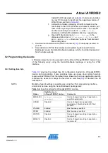
c.  Make sure that the driver is installed successfully and the new COM 

port is present in the device list. Check that the device is correctly 

shown in the Device Manager window, as i

Figure 8-1

. 

Figure 8-1. 

Correctly installed COM port for MeshBean device.


Summary of Contents for AVR2052

Page 1: ...r Atmel ZigBee compliant wireless sensor network The SDK provides a complete software and documentation toolkit for prototyping developing and debugging custom applications on top of the BitCloud appl...

Page 2: ...following hardware platforms are supported by the BitCloud SDK Table 2 1 Supported hardware platforms Name in this document Platform MCU RF Supported modules Supported external flash for OTAU Support...

Page 3: ...AT91SAM7X256 AT86RF230 or AT91SAM7X256 AT86RF212 N A N A AT91SAM7X EK and RZ600 radio boards BitCloud for SAM7X EK Please note that this document describes the use of the Atmel BitCloud SDK with the s...

Page 4: ...ibed in detail in Chapter 4 Starting the development of new or modifying existing applications based on the BitCloud C API as shown in Chapter 5 The BitCloud SDK is available for several platforms as...

Page 5: ...coordinator to emulate sensor data and demonstrate data transmission End devices follow a duty cycle that is the microcontroller and radio transceiver are put to sleep periodically and wake up to tra...

Page 6: ...board In order to make initial setup easier there are a number of pre compiled images provided with the SDK that can be used right away without any modification Atmel ZigBit platform does not require...

Page 7: ...in search of a network with the specified extended PAN ID By default the channel mask for all application images provided with the SDK contains a single channel In rare cases if the frequency correspo...

Page 8: ...2 It is presented in graph and table form Other parameters can be observed for each node in table form The node data pane includes a sensor selection combo box which is used to switch between sensor...

Page 9: ...gy pane A corresponding option can be selected in the node link parameters from the quick settings toolbar The user can select any node in the topology pane to monitor the node s activity and see the...

Page 10: ...shown in Figure 4 3 b Specify Connection settings to match the port where the Runner device is connected c Click the Init button to force the program to collect information about the node s configura...

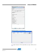
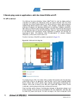
Page 11: ...el AVR2052 11 8200M AVR 11 11 Figure 4 3 Bootloader PC tool s main screen Figure 4 4 Bootloader PC tool s devices screen For complete description of OTAU implementation and usage in BitCloud refer to...

Page 12: ...ignificantly reduce application complexity and simplify the development effort The BitCloud Stack Documentation 1 provides detailed information on the stack s C API and its use The main structure of t...

Page 13: ...h where sample applications may be modified compiled and debugged 2 A corresponding compiler toolchain for example WinAVR IAR or YAGARTO which provides everything necessary to compile application sour...

Page 14: ...ork functionality of software and additional network visualization with WSNMonitor See Chapter 4 X X X X X X Blink Introduces the simplest application that uses timer and LEDs When started the applica...

Page 15: ...n the aps file from the appropriate directory with Atmel AVR Studio 4 and execute Build Rebuild All from the main menu Once the build process is completed hex srec bin and elf application images will...

Page 16: ...in the iar_projects Debug exe subdirectory for WSNDemo in the Applications WSNDemo iar_projects Debug exe directory with format as specified in Linker Output Options of the IAR project 5 3 Reserved ha...

Page 17: ...fic details are given in the corresponding sections in the appendices For detailed description of the Serial Bootloader package the list of supported platforms instructions on generating SREC images e...

Page 18: ...he required node by clicking on it Node titles displayed on the topology pane do not show node destinations The displayed titles do not necessarily relate to the node functions but they can be redefin...

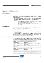
Page 19: ...l voltage is 3V for MeshBean and MeshBean 900 boards 3 3V for MeshBean Amp Using an AC DC adaptor automatically disconnects the AA batteries Using the USB port disconnects the AC DC adaptor 8 1 2 1 Co...

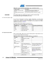
Page 20: ...Bit MCU pin assignment DataFlash pin ATZB XX pin Internal ATmega1281 MCU pin MISO USART0_RXD 38 PE0 MOSI USART0_TXD 39 PE1 CLOCK USART0_EXTCLK 40 PE2 CS ADC_INPUT3 30 PE3 8 1 3 System requirements Bef...

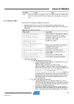
Page 21: ...Components BSP Source header and library files for the BitCloud BSP SDK Root BitCloud lib Library files for the BitCloud stack SDK Root Applications Source files for the sample applications 2 Install...

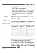
Page 22: ...serial RS 232 ports share the same physical port on the board and thus cannot be used at the same time Keep in mind that the connection mode is controlled by setting a jumper on a MeshBean board Refe...

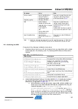
Page 23: ...tings is possible only using the JTAG or ISP programming interfaces and cannot be done with Serial Bootloader Table 8 7 Fuse bit settings for ZigBit ZigBit Amp and ZigBit 900 Option Default value in A...

Page 24: ...s from a dedicated UID chip available on the MeshBean board via the 1 Wire interface If there is no such UID then a zero MAC address will be assigned to the device Note that for proper operation all n...

Page 25: ...a description of how the images can be programmed to the devices using JTAG 8 2 5 Programming with ISP Refer to AVR Studio 3 documentation for a description of how firmware images can be programmed to...

Page 26: ...Set up the hardware as described in Section 8 1 2 2 Install the Atmel BitCloud SDK as described in Section 8 1 4 3 Program one device with the coordinator image file and other with either the router...

Page 27: ...be converted to srec format and installed using the Bootloader PC tool from the same package as described in Section 4 5 3 The device is now able to perform as an OTA client as defined in 30 The above...

Page 28: ...ke sure that all necessary hardware is available For ATRF4CE EK o Two or more RCB128RFA1 boards with 2 4GHz antennas and AAA batteries o one or more RCB breakout boards other boards from the kit may b...

Page 29: ...pdate the STK600 firmware if suggested 5 Go to the HW Settings tab 6 Specify 3 3V in the VTarget field and press Write The actions above must be performed only once for each ATSTK600 board 9 1 2 1 OTA...

Page 30: ...use image files for evaluating WSNDemo Refer to Section 9 3 for a description of the images SDK Root Evaluation Tools WSNDemo WSN Monitor WSNMonitorSetup exe WSNMonitor installer SDK Root BitCloud Com...

Page 31: ...oaded into the Atmel ATmega128RFA1 device in one of the following ways using the Serial Bootloader package or using the JTAG interface 9 2 1 Setting fuse bits Table 9 4 provides the default fuse bit c...

Page 32: ...g with Serial Bootloader is not allowed and so firmware can be uploaded only over the JTAG interface Default fuse bytes equal in this order extended fuse byte high fuse byte low fuse byte 0xFF 0x99 0x...

Page 33: ...a1 directory in the package The Bootloader_ATmega128RFA1_RCB_BB_RS232 hex file for RCB128RFA1 The Bootloader_ATmega128RFA1 hex file for ATAVR128RFA1 EK1 In both cases the fuse bits should be configure...

Page 34: ...eating a small ZigBee network right away The image name is formed according to the following scheme WSNDemo_ board _ MCU _ role extension To specify the node role put Coord Router or EndDev for coordi...

Page 35: ...ded bootloader bootloaderOTAU_ATmega128RFA1 hex file from the Serial Bootloader package b The application image should be converted to srec format and installed using the Bootloader PC tool from the s...

Page 36: ...1 Install the J12 and J16 extension headers on the board if not already installed 2 Install the JTAG pin header on the board if not already installed 3 Use several two wire cables to connect J16 pins...

Page 37: ...cture Directory file Description SDK Root Documentation Documentation for the Atmel BitCloud software SDK Root Evaluation Tools WSNDemo Embedded Ready to use image files for evaluating WSNDemo Refer t...

Page 38: ...he Atmel UC3 device using JTAG Programming the device using the serial bootloader is not supported 10 2 1 Setting fuse bits Table 10 4 provides the fuse bit configuration that should be loaded into At...

Page 39: ...20 by running following command in the console avr32program program finternal 0x80000000 256Kb cxtal e v O0x80000000 filename elf Make sure the proper fuse options in the JTAGICE mkII Fuse JTAGICE 3 F...

Page 40: ...ctivity can be monitored in two ways Observing LEDs on the development boards as described in Table 10 5 The LEDx label corresponds to the EVK1105 board Monitoring network topology information through...

Page 41: ...kII or Atmel JTAGICE 3 11 1 2 Hardware setup For REB2xxED EK please refer to 34 for hardware setup instructions Atmel STK600 boards require the following setup to use with ATxmega 1 Attach the ATxmega...

Page 42: ...built in DataFlash and so to use OTAU on an STK600 it is sufficient to connect the SI SO SCK and CS pins under the DataFlash pin heading to the corresponding MCU pins noted in Table 11 1 Table 11 1 Ex...

Page 43: ...rary files for the BitCloud BSP SDK Root BitCloud lib Library files for the BitCloud stack SDK Root Applications Source files for the sample applications 2 Install the selected IDE e For IAR Embedded...

Page 44: ...some use cases when certain fuse bits require values different from the default ones Based on their own application specific requirements users can change the fuse bits as well See 33 for detailed fu...

Page 45: ...lication image must be built separately for each board 11 2 3 Programming with Serial Bootloader Programming using Serial Bootloader requires that the embedded bootloader code is loaded to the device...

Page 46: ...JTAG to program the microcontroller will erase the embedded bootloader making the loading of application images with Serial Bootloader impossible until the embedded bootloader firmware is reprogramme...

Page 47: ...ult images are preconfigured to use Extended PAN ID 0xAAAAAAAAAAAAAAAA and operate on channel 0x0F for RF231 and RF230 radios or channel 0x01 and channel page 0 for RF212 radio 11 4 Running WSNDemo 11...

Page 48: ...as described in Section 4 5 3 c The device is able to act as an OTA client as defined in 30 2 Program another device with the Runner application available in the SDK Root Evaluation Tools Runner direc...

Page 49: ...e 12 1 SAM7X EK to RZ600 radio board pin mapping SAM7X EK J16 pin Radio board pin Pin name A10 1 Reset N A 2 Misc A31 3 Interrupt A9 4 Sleep transmit A15 5 Chip select A18 6 MOSI A17 7 MISO A19 8 SCK...

Page 50: ...ion Documentation for the Atmel BitCloud software SDK Root Evaluation Tools WSNDemo Embedded Ready to use image files for evaluating WSNDemo Refer to Section 12 3 for a description of the images SDK R...

Page 51: ...uploaded into AT91SAM7X EK device using the JTAG interface Programming device using the serial bootloader is not supported 12 2 1 Extended MAC address assignment For proper operation all nodes in a Zi...

Page 52: ...econfigured to use Extended PAN ID 0xAAAAAAAAAAAAAAAA and operate on channel 0x0F for RF231 and RF230 radios or channel 0x01 and channel page 0 for RF212 radio 12 4 Running WSNDemo 12 4 1 Starting WSN...

Page 53: ...Hardware resources reserved by the stack on AT91SAM7X256 Resource Description SPI0 Radio interface ARM ports PA8 PA9 PA14 PA16 PA17 PA18 PA30 Radio interface Timer2 Microsecond timer Timer0 System tim...

Page 54: ...eiver for each SAM3S EK board o Atmel AT91SAM ICE JTAG emulator For RF231USB RD o Two or more RF231USB boards o Atmel AT91SAM ICE JTAG emulator 13 1 2 Hardware setup For SAM3S EK connect the RZ600 rad...

Page 55: ...he Atmel BitCloud software SDK Root Evaluation Tools WSNDemo Embedded Ready to use image files for evaluating WSNDemo Refer to Section 13 3 for the description of the images SDK Root Evaluation Tools...

Page 56: ...nality cannot be demonstrated with a stock SAM3S EK kit as there is no external EEPROM on these boards It is also not enabled in reference applications and pre built binaries provided with the SDK 13...

Page 57: ...rd the application should enable the DFU support turned on in the application s configuration h file Otherwise after loading the application via Serial Bootloader tools loading another image will not...

Page 58: ...3 4 2 Monitoring WSNDemo activity Network activity can be monitored in two ways Observing the SAM3S EK board s color LEDs see Table 13 3 Monitoring network topology information through WSNMonitor inst...

Page 59: ...2 end device IEEE address 8 bytes IEEE address of the sending node Short address 2 bytes Short address of the sending node Version 4 bytes Version of the WSNDemo application protocol used by the sendi...

Page 60: ...Sensor data for board type 1 Used for MeshBean boards 0x20 Node name Please note that in the current version of WSNDemo devices send additional fields of type 0x01 sensor readings for boards of type 1...

Page 61: ...e basically the messages wrapped as defined below Table 15 1 Serial message format Offset Length Description 0 2 bytes Start sequence 0x10 0x02 2 N bytes Variable length payload the message received f...

Page 62: ...board description 17 Radio Extender Board REB231 V4 0 2 18 ATEVK1105 description 19 32 bit AVR UC3 Software Framework 1 5 0 20 AVR32 GNU Toolchain 21 IAR Embedded Workbench for Atmel 32 bit AVR 22 IAR...

Page 63: ...Atmel AVR2052 63 8200M AVR 11 11 36 RF231USB User Guide...

Page 64: ...eference applications 14 5 2 2 Supported toolchains 15 5 3 Reserved hardware resources 16 6 Serial Bootloader and OTAU 17 7 Basic troubleshooting 17 8 Appendix A 2 ZigBit specifics 19 8 1 Getting star...

Page 65: ...x A 4 UC3 specifics 36 10 1 Getting started 36 10 1 1 Required hardware 36 10 1 2 Hardware setup 36 10 1 3 System requirements 36 10 1 4 Installing the SDK 37 10 2 Programming the boards 38 10 2 1 Set...

Page 66: ...ng WSNDemo 52 12 4 1 Starting WSNDemo 52 12 4 2 Monitoring WSNDemo activity 52 12 5 Reserved hardware resources 53 13 Appendix A 7 SAM3S specifics 54 13 1 Getting started 54 13 1 1 Required hardware 5...

Page 67: ...ht is granted by this document or in connection with the sale of Atmel products EXCEPT AS SET FORTH IN THE ATMEL TERMS AND CONDITIONS OF SALES LOCATED ON THE ATMEL WEBSITE ATMEL ASSUMES NO LIABILITY W...

Reviews: