3
Installation Guide
AT-HDR-EX-70C-KIT
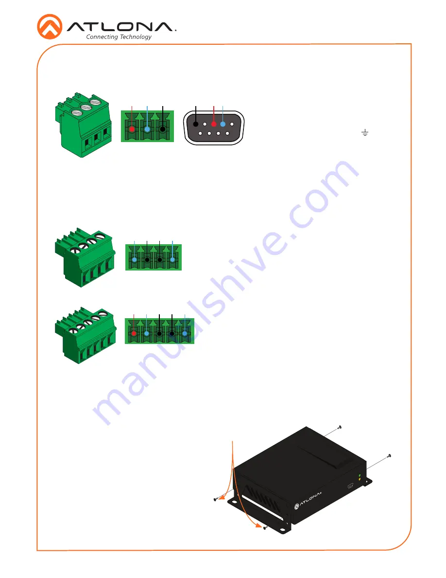
Pin out will be determined by the
RS-232 cable and connect as
RX (receive), TX (transmit) and
(Ground).
A 3-pin captive screw connector for RS-232 has been included.
Two captive screw connectors for IR have been included. A 4-pin connector for the transmitter
and a 3-pin connector for the receiver.
IR IN
is connected by a power, ground, and signal
wire. Use a 12V IR receiver with it
(
e.g.
AT-IR-CS-RX
purchasable through atlona.com)
.
IR IN
is connected by a ground and signal wire. Use
with 3rd party control systems. For easy termination,
Atlona recommends using the 2 meter IR cable AT-LC-
CS-IR-2M
(purchasable through atlona.com)
.
IR OUT
is connected by a ground and signal wire.
Use the included IR emitter with this port.
IR OUT
is connected by a ground and signal wire.
Use the included IR emitter with this port.
RS-232
IR
IR IN
IR OUT
GND
S
S
P
GND
RX
TX
GND
RX
TX
IR IN
IR OUT
GND
S
S
The AT-HDR-EX-70C-KIT includes two mounting brackets and four mounting screws each, which
can be used to attach the units to any flat surface.
1. Position one of the mounting brackets,
as shown below, aligning the holes on
the side of the enclosure with one set of
holes on the mounting bracket.
2. Use the enclosure screws to secure the
mounting bracket to the enclosure.
3. Repeat the above steps to attach
the second mounting bracket to the
opposite side of the unit.
Mounting Instructions
FW
AT-HDR-EX-70C-RX
POWER
LINK
Included screws


