2
Installation Guide
AT-HDR-EX-70C-KIT
AT-HDR-EX-70C-RX
POWER
LINK
FW
RS-232
RX TX
S
S
P
HDBaseT IN
HDMI OUT
IR OUT
IR IN
DC 48V
-
+
RS-232
RX TX
S
S
HDBaseT OUT
HDMI IN
IR OUT
IR IN
AT-HDR-EX-70C-TX
POWER
LINK
TEST
UTILITY
1. LINK
2. FW
3. TEST
4. 5V LOCK
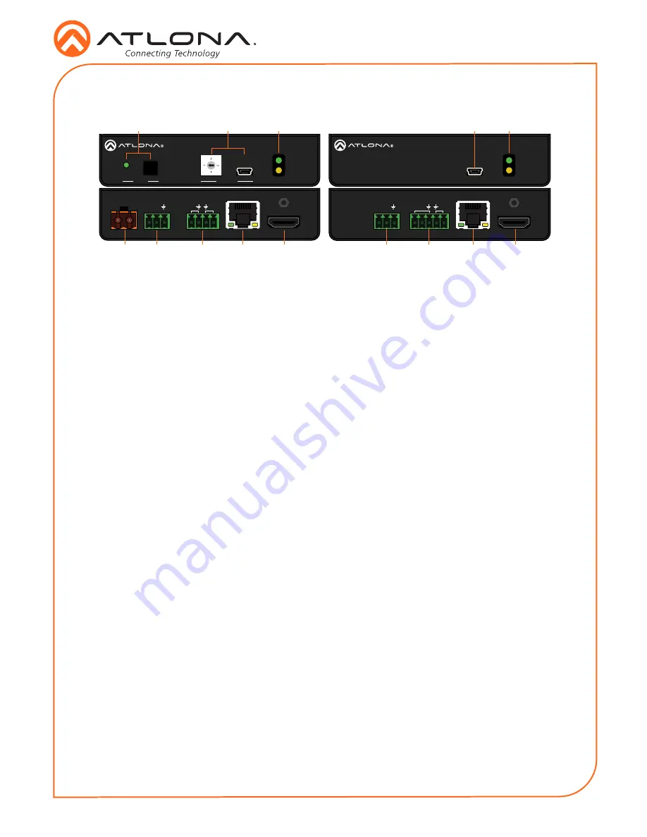
Panel Descriptions
1
TEST
Quick and easy test for cables. Use the
button to start the test and the LED to
determine pass or fail.
2
UTILITY
Connect a mini-USB to USB-A cable from
this port to a computer for updating and
testing. Rotate the dial to set the unit into
different modes.
3
POWER and LINK LEDs
The power LED will illuminate green when
receiving power. The link LED will glow
yellow when signal is being sent/received
between the transmitter and the receiver.
4
DC 48V
Connect the included power supply to this
port.
5
RS-232
Bidirectional control port, used for pass
through of commands to or from the
receiver.
6
IR
Connect a 3rd party controller to the IR IN
port or an IR emitter to the IR OUT port.
7
HDBaseT OUT
Connect an HDBaseT cable from this port
to the
HDBaseT IN
port on the receiver.
8
HDMI IN
Connect an HDMI cable from a source to
this port. e.g. HDR BluRay Player
9
FW
Connect a mini-USB to USB-A type cable
from this port to a computer, to update
the firmware.
10 POWER and LINK LEDs
The power LED will illuminate green when
receiving power. The link LED will glow
yellow when signal is being sent/received
between the transmitter and the receiver.
11 RS-232
Bidirectional control port, used for pass
through of commands to or from the
receiver.
12 IR
Connect an IR receiver to the IR IN port or
an IR emitter to the IR OUT port.
13 HDBaseT IN
Connect an HDBaseT cable from this
port to the
HDBaseT OUT
port on the
transmitter.
14 HDMI OUT
Connect an HDMI cable from this port to
an HDMI display.
11
5
6
7
8
12
14
13
4
10
3
9
2
1


