REV. 01 2012
21 / 35
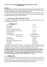
6.4.4 ALU MODES
All the ALU modes are dynamic balance. The program of this machine includes seven ALU balancing
modes from ALU1 to ALU7 for application of alloy rims with the different profiles (ref. fig. 33).
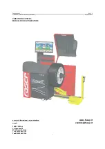
To perform the ALU balancing, do as follows:
x
Select the mode that best fits the available
locations.
x
Measure and set the wheel dimensions
automatically or manually.
x
Start a spin.
x
Following the procedure described in the chapter
6.4.1.1 and 6.4.1.2 for DYNAMIC mode to locate
the unbalanced positions for both inner side and
outer side of the rim.
x
Apply the correct weights on the positions (ref. fig.
35). The adhesive weights can be applied by using
the pusher of the A/D gauge.
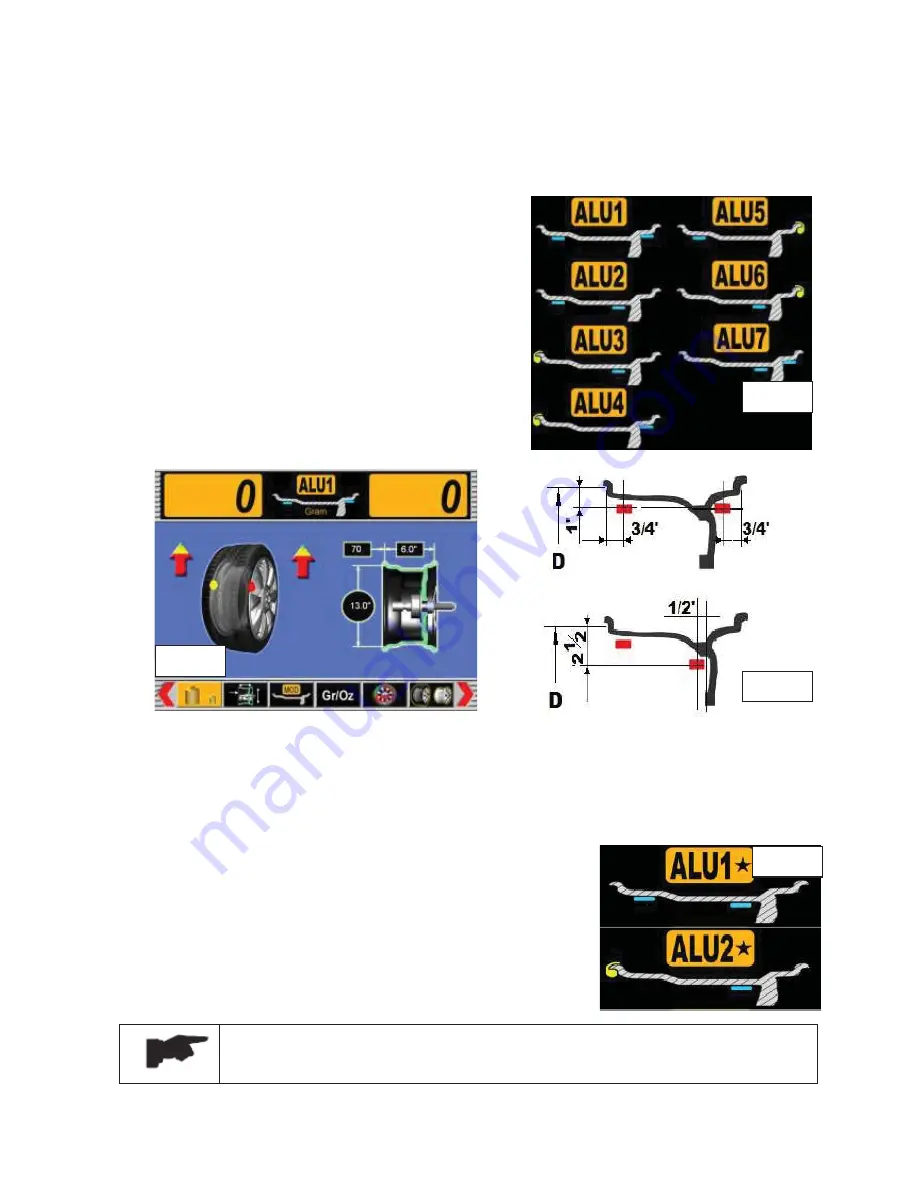
6.4.5 ALU
ƿ
ƿ
MODES
ALU
ƿ
modes are used to get the precise positions of alloy rims for application of the weights by
using the A/D gauge directly and to avoid the approximate errors of standard ALU functions..
The program of this machine includes two ALU
ƿ
modes: ALU1
ƿ
and ALU2
ƿ
(ref. fig. 36):
x
ALU1
ƿ
mode is used to apply the adhesive weights on the
rim for correction.
x
ALU2
ƿ
mode is used to clip the weights on the rim for
correction.
Be sure to set the wheel dimensions correctly following the chapter 6.3.2.2.
Failure to do so, the correct balancing cannot be obtained.
B sure the positions of the rim for application of adhesive weights are clean.
Fig. 33
Fig. 34
Fig. 35
Fig. 36
Summary of Contents for WB55
Page 1: ......
Page 35: ...REV 01 2012 35 35 CHAPTER 12 ELECTRIC DIAGRAM...