REV. 01 2012
15 / 35
6.2.1
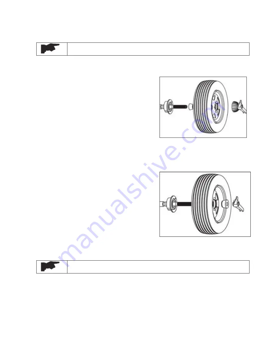
STANDARD BACK CONE MOUNTING (ref. Fig. 12)
Carefully clean the component surface before performing any operation.
Most steel wheels can be mounted properly using this method. The wheel is centered on a cone from
the inner side of the hub.
x
S
elect the cone that best fits the centre hole in the
wheels. Slide the cone onto the shaft with the
large end towards the faceplate.
x
L
ift the wheel onto the shaft and centre it on the
cone.
x
A
ttach the pressure cup to the quick locking nut
and install the assembly onto the shaft. Tighten
securely.
6.2.2 STANDARD FRONT CONE MOUTING (ref. Fig. 13)
A wheel should be centered by the outer side of the hub only when the inner surface will not provide
an accurate surface to center on.
x
S
elect the cone that best fits the center hole in the
wheel.
x
L
ift the wheel onto the shaft and slide it back
against the shaft faceplate.
x
Slide the cone onto the shaft and into the center
of the wheel. You will need to lift the wheel to
seat the cone in the centre hole.
x
I
nstall the quick locking nut (without the pressure
cup) onto the shaft. Tighten securely against the
cone
6.3
SETTINGS OF WHEEL DIMENSIONS
Before balancing a wheel, wheel dimensions must be measured correctly.
6.3.1
WHEEL DIMENSIONS
6.3.1.1
STANDARD MODES
Measure the wheel dimensions as shown in the figure 14
6.3.1.2
ALU
ƿ
ƿ
MODES
Measure the wheel dimensions as shown in the figure 15.
Fig. 12
Fig. 13
Summary of Contents for WB55
Page 1: ......
Page 35: ...REV 01 2012 35 35 CHAPTER 12 ELECTRIC DIAGRAM...


