background image

17

I

NSTRUCTION MANUAL

F

UEL SYSTEM

The fuel filter assembly strains out water and impurities from the
fuel. 

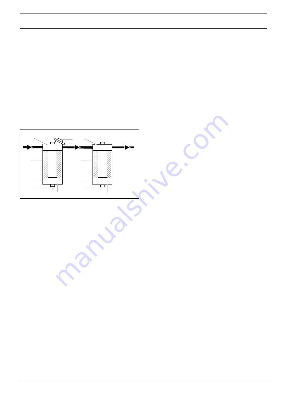
The fuel is drawn from the tank the through the fuel pre-filter (FF1)
and the fuel fine-filter (FF2) to the engine injection pump.

Only one third of the fuel drawn is used for combustion. The
remnant is used to cool the injection pump and is returned to the
tank via a fuel cooler.

The fuel cooler is located behind the grating at the right-hand side of
the compressor.

The fuel filters each consist of an adapter head, a spin-on filter
element and a waterseparator bowl.

DV1,2 Drain valve

1

Adapter head

FF1

Fuel pre-filter

2

Filter element

FF2

Fuel fine-filter

3

Filter bowl

VP1,2

Vent plug

4

Hand-pump

Draining the fuel pre-filter

1. Open the bowl drain valve (DV1) and pump water out.

2. Close the drain valve.

Draining the fuel fine-filter

1. Open the bowl drain valve (DV2) to evacuate water.

2. Close the drain valve.

Replacing the fuel pre-filter element

1. Drain the fuel from the bowl.

2. Remove the filter and separate the bowl from the element.

3. Apply a film of gas oil to the new bowl seal.

4. Screw the bowl to the new element tightly by hand.

5. Apply a film of gas oil to the new element seal.

6. Screw on the filter tightly by hand.

7. Open the head vent and operate the pump. Close the vent when

fuel begins to purge.

8. Check for leaks, retighten if necessary.

Replacing the fine-filter element

1. Drain from the bowl.

2. Remove the filter and separate the bowl from the element.

3. Apply a film of gas oil to the new bowl seal.

4. Screw the bowl to the new element tightly by hand.

5. Apply a film of gas oil to the new element seal.

6. Fill the element with fuel and screw on the filter tightly by hand.

7. Check for leaks, retighten if necessary.

C

OOLANT

The coolant is a mixture of water and anticorrosion/antifreeze agent.
The coolant must remain in the system all the year round to ensure
adequate corrosion protection and to increase the boiling point.
Renew the coolant every two years, as the corrosion protection
diminishes.

It is not permitted to use water alone as a coolant even if antifreeze
properties are not required. The water in the coolant has to satisfy
certain requirements, which are frequently, but not always, met by
drinking water. If the quality of the water is insufficient, the water
has to be treated. Information regarding this can be obtained from
any Mercedes-Benz Service Station.

The portion of anticorrosion/antifreeze agent in the coolant must not
drop below 40 % by volume during operation (equals antifreeze
protection down to approximately -25 ¡C). A lower portion does not
adequately ensure the anticorrosive properties. 

To avoid any damage to the cooling system:

Ð

Use only approved anticorrosion/antifreeze agents. Information
is available from any Mercedes-Benz Service Station.

Ð

When replenishing the system (after loss of coolant) it is
essential to ensure an anticorrosion/antifreeze portion of 50 %
by volume (antifreeze protection down to -37 ¡C).

Ð

Do not use more than 55 % by volume of anticorrosion/
antifreeze agent (= maximum antifreeze protection). Otherwise
the antifreeze properties will be reduced and the heat dissipation
impaired.

In exceptional cases, where it is evident that no anticorrosion/
antifreeze agent can be obtained and no antifreeze protection is
required (e. g. tropics), 1 % by volume = 10 cm

3

/litre of corrosion

protection oil must be added. In such cases, renew the coolant
annually.

DV1

1

2

FF1

VP1

3

4

DV2

1

2

FF2

VP2

3

Summary of Contents for XRVS455 Md

Page 1: ...ables 99 Instruktionsbok för transportabla kompressorer 123 Istruzioni per l uso di compressori mobili 147 Instruksjonsbok for transportable kompressorer 171 Betjeningsvejledning for mobile kompressorer 195 BÈ Ï Ô Ô ËÁÈÒÓ ÁÈ ÊÔÚËÙÔ Û Ì ÈÂÛÙ 219 Manual de instruções para compressores portáteis 243 Siirrettävien kompressorien käyttöohjeet 267 Parts list Onderdelenlijst Liste de pièces Ersatzteillist...

Page 2: ...2 XRVS455 Md ...

Page 3: ...peration 13 Stopping 13 Maintenance 14 Preventive maintenance schedule 14 Notes 15 Battery care 15 Storage 15 Service pak 15 Oil specifications 15 Change of oil and oil filters 15 Adjustments and servicing procedures 16 Air filters 16 Coolers 16 Safety valve 16 Fuel system 17 Coolant 17 Shutdown switches 18 Brake adjustment 18 Belt tensioning adjustment 18 Problem solving 19 Alternator precautions...

Page 4: ...starting In addition a warning sign bearing a legend such as Òwork in progress do not startÓ shall be attached to the starting equipment On engine driven units the battery shall be disconnected and removed or the terminals covered by insulating caps On electrically driven units the main switch shall be locked in open position and the fuses shall be taken out A warning sign bearing a legend such as...

Page 5: ...he open end is held securely A free end will whip and may cause injury Never play with compressed air Never apply it to your skin or direct an air stream at people Never use it to clean dirt from your clothes When using it to clean down equipment do so with extreme caution and use eye protection Do not use compressed air from any type of compressor without taking extra measures for breathing purpo...

Page 6: ...e gas mixture forms in the cells and might escape through the vent holes in the plugs Thus an explosive atmosphere may form around the battery if ventilation is poor and can remain in and around the battery for several hours after it has been charged Therefore Ð never smoke near batteries being or having recently been charged Ð never break live circuits at battery terminals because a spark usually...

Page 7: ...meeting local safety regulations shall be applied Never shall cables chains or ropes be applied directly on or through lifting eyes Never allow sharp bends in lifting cables chains or ropes 10 Lifting hooks eyes shackles etc shall never be bent and shall only have stress in line with their design load axis The capacity of a lifting device diminishes when the lifting force is applied at an angle to...

Page 8: ...pressure of 25 bar 365 psi The compressor is driven by a liquid cooled diesel engine manufactured by MERCEDES An overview of the main parts is given in the diagram below 8 XRVS455 Md T AV FT SV OF AR OS OFP MPV H22 1 E 5 OFe B SG CE FC1 4 FT FC1 EB FP FF1 FF2 RV TG 80 10 0 0 20 40 60 80 10 0 0 20 40 60 80 10 0 0 20 40 60 PG 3 FC2 DS AF SR FC3 2 F ...

Page 9: ...g valve SG Sight glass SR Speed regulator engine SV Safety valve T Towbar TG Temperature gauge BODYWORK The compressor the engine the cooling system etc are enclosed in a sound insulated bodywork that can be opened by means of side front and rear service doors A lifting eye is provided under a small door on top of the compressor MARKINGS AND INFORMATION LABELS Markings 9 INSTRUCTION MANUAL Compres...

Page 10: ...e starts building up S20 Emergency push button To stop the compressor in case of emergency This is done by pushing the red button on the door of the control panel To reset the push button press it and turn it anticlockwise Use this button only in case of an emergency Gauges WPG Working pressure gauge P1 Fuel level gauge P2 Engine oil pressure gauge P3 Hourmeter P4 Temperature gauge engine coolant ...

Page 11: ...n the air receiver TG Compressor element air outlet temperature gauge Located behind the front service door and indicates the temperature of the air at the outlet of the compressor element PG Pressure gauge low pressure compressor element Located behind the front service door The gauge indicates the pressure after the first compression stage or in other words after the low pressure compressor elem...

Page 12: ...pressor element low pressure CELP Compressor element high pressure CV Check valve DP1 Drain plug oil cooler DP2 Drain plug air receiver DP3 Drain plug check valve DP4 Drain plug oil stop valve E Engine F Fan FR Flow restrictor oil scavenging line MPV Minimum pressure valve with none return valve OC Oil cooler OF Oil filter OFP Oil filler plug OSE Oil separator element OSV Oil stop valve RV Regulat...

Page 13: ...and the engine oil pressure lamp will light up 2 Press the START button and hold until the engine fires The alternator charging indication lamp and the engine oil pressure lamp will extinguish when the alternator supplies power and the oil pressure has built up Notes 1 The start prevention switch S18 prevents the engine from starting as long as the pressure in the vessel exceeds 1 6 bar 2 To resta...

Page 14: ...lean Check Clean Check Clean Electrolyte and terminals of batteries Check Check Check Tension and condition of belts Check Check Check Routing and condition of flexible hoses Check Check Check Oil water fuel system Check for leaks Check for leaks Check for leaks Flexible joints and pivots of engine stop solenoid Lubricate Lubricate Lubricate Flexible joints and pivots of speed regulator Lubricate ...

Page 15: ...ECIFICATIONS Engine It is strongly recommended to use Atlas Copco Par Oil SAE 15W40 which is specially selected to keep the engine in excellent condition Ð 5 litre can 1615 5953 00 Ð 20 litre can 1615 5954 00 Ð 208 litre drum 1615 5955 00 If it is desired to use another brand of oil consult the engine instruction manual for oil specifications viscosity recommen dations and oil change intervals Com...

Page 16: ...e latter 3 Clean the dust trap and baffle and reassemble them taking care that the slot in the baffle fits over the stud of the trap 4 Reinstall the dust trap on the filter body with the side marked TOP upwards and secure it with the clips Never use oil in the traps COOLERS Keep the coolers clean to maintain the cooling efficiency Service doors are provided in both sides of the fan cowl to allow e...

Page 17: ...eal 6 Fill the element with fuel and screw on the filter tightly by hand 7 Check for leaks retighten if necessary COOLANT The coolant is a mixture of water and anticorrosion antifreeze agent The coolant must remain in the system all the year round to ensure adequate corrosion protection and to increase the boiling point Renew the coolant every two years as the corrosion protection diminishes It is...

Page 18: ...e switch and remove the latter with its coupling from the air intake chamber 2 Fit the switch to a tee Connect a vacuum gauge and a hose or pipe to the tee 3 Reconnect the wires to the switch and press the on off push button 4 Create a vacuum with the mouth through the hose while observing the vacuum gauge and the filter servicing alarm lamp The lamp should light up when the vacuum has reached the...

Page 19: ...e polarity and connect the batteries correctly 2 3 5 4 1 6 7 Problem 1 Lamp H1 does not light up when pressing S1 2 Starter motor does not crank engine after pressing S1 and depressing S3 3 Starter motor cranks engine when depressing S3 but engine does not fire 4 Engine fires but lamp H1 remains alight 5 Engine starts but shuts down after approx 10 seconds Possible faults a Defective or discharged...

Page 20: ...alve remains partially closed h Safety valve leaking i Bleed off valve leaking Corrective actions d Stop at once Test switches replace as necessary e Fill coolant tank a Replace a Remove and dismantle Correct as necessary b See 11f c See 12b a If air blows from venting devices remove and dismantle valve Replace membrane b See 11f a Unscrew filler plug one turn and wait until all pressure is releas...

Page 21: ... h Oil stop valve malfunctioning i Oil separator element clogged Corrective actions a Dismantle and inspect parts b Check hoses and their fittings Stop leaks replace leaking hoses c Remove dismantle and inspect piston ring and its O ring Replace worn or defective parts d See 11f e Remove and inspect valve f Remove and inspect valve a See the instruction manual of the engine b Start compressor whil...

Page 22: ...ut use of the handpump Always make sure the filter in the fuel suction pipe is not clogged Refer to page 394 PRESSURE REDUCER The pressure reducer option is available for the compressors with a normal working pressure of 17 20 or 25 bar The pressure reducer will reduce the high pressure to 7 bar The option provides an extra outlet cock so other applications which require a lower pressure can also ...

Page 23: ...cooler cools the outlet air The condensation formed by the cooling is separated by the waterseparator Any final oil and humidity is eliminated by the fine filter A pressure decrease will appear due to the installation of the aftercooler waterseparator and fine filter The pressure gauge indicates the pressure in front of the aftercooler As a result the outlet pressure will always be a little less t...

Page 24: ...ssion stages 2 Maximum unloading pressure 27 bar e Normal working pressure 25 bar e up to altitude of 4 5000 m Minimum working pressure 15 bar e Free air delivery 5 450 l s Compressor cooling system oil Mercedes diesel engine water cooled OM 442 LA Engine speeds Maximum load speed 1700 r min Unloading speed 1050 r min Electrical system negative earthed 24 V Batteries Number 2 Voltage capacity 12 V...

Page 25: ...m3 min 35 315 cfm 1 mbar 0 401 in wc 1 N 0 225 lbf 1 Nm 0 738 lbf ft tûF 32 1 8 x tûC tûC tûF 32 1 8 Ð A temperature difference of 1 ûC a temperature difference of 1 8 ûF DATAPLATE ATLAS COPCO AIRPOWER n v MADE BY ATLAS COPCO AIRPOWER n v WILRIJK BELGIUM 1615 6945 00 YA3 00 kg 1 kg 2 kg p max e working betrieb service Speed Drehzahl Regime p engine motor moteur Manuf year Baujahr AnnŽe de fabricat...

Page 26: ...26 XRVS455 Md ...

Page 27: ...t diagrams Elektrische schema s Schémas de circuits Schaltpläne Esquema de conexiones Kopplingsscheman Diagrammi dei circuiti Kretsskjema Kredsløbsdiagrammer È ÁÚ ÌÌ Ù Î ÎÏˆÌ ÙˆÓ Esquemas eléctricos Sähkökaaviot ...

Page 28: ...W X1 3 3 X1 4 4 X1 5 5 X1 6 6 X1 7 7 X1 8 8 5 5 6 6 7 7 8 8 9 9 10 10 11 11 12 12 13 13 14 14 14 14 13 13 12 12 11 11 10 10 9 9 8 8 7 7 6 6 5 5 4 4 3 3 2 2 1 1 4 4 3 3 2 2 1 1 H1 H2 H3 H9 H8 H10 H7 H11 H24c H24b H24a S4 S3 S1 A B C D E CIRCUIT DIAGRAM DIAGRAMMA DEL CIRCUITO ELEKTRISCH SCHEMA KRETSSKJEMA SCHEMA DE CIRCUIT STRØMDIAGRAM VERDRAHTUNGSPLAN π ƒ ªª Y Ïøª DIAGRAMA DE CIRCUITOS DIAGRAMA DOS...

Page 29: ...12 19 18 16 17 14 13 42 11 10 9 9 10 11 12 13 14 15 16 17 18 19 20 16 16 11 20 15 1 M 16 17 18 19 20 21 22 23 24 25 26 27 28 29 30 31 32 33 B7 B8 S13 B12 S14 S10 X12 X12 X15 X15 X14 G W Dp P X1 9 9 X1 10 10 X2 11 11 X2 12 12 X2 13 13 X2 14 14 X2 16 16 X2 17 17 X2 18 18 X2 19 19 X2 15 15 X2 20 20 10 10 9 9 8 8 7 7 6 6 5 5 4 4 3 3 2 2 1 1 11 11 12 12 X8 X8 G G G X7 P4 P3 X7 X7 h G G G X6 P2 X6 X6 W ...

Page 30: ...e moteur Ausschalter Motoršldruck S7 8 Shut down switch compressor element temperature Stopschakelaar temperatuur kompressorelement Interrupteur dÕarr t tempŽrature ŽlŽment compresseur Ausschalter Temperatur Kompressorelement S10 Pressure switch airfilter Drukschakelaar luchtfilter Pressostat filtre ˆ air Druckschalter Luftfilter S13 Pressure switch load prevention Drukschakelaar verhinderen van b...

Page 31: ...r de parada temperatura del elemento del compresor SŠkerhetsstoppstršmstŠllare temperaturen fšr kompressorns Interruttore di arresto temperatura elemento compressore Bryter for sikkerhetsstopp ved ukorrekt temp pŒ element kompress element S10 Presostato filtro de aire VakuumstršmstŠllare luftfilter Interruttore pressione filtro dellÕaria Trykkbryter for luftfilter S13 Interruptor de presi n preven...

Page 32: ...aragem temperat do elemento do compr Kompressorin lŠmpštilavahti S10 Trykafbryder luftfilter È Îfi ÙË ÂÛË Ê ÏÙÚÔ ÚÔ Contactor de press o do filtro de ar Ilmansuodattimen painekytkin S13 Trykafbryder til forhindring af belastning ÚfiÏË Ë ÊÔÚÙ Ô È Îfi ÙË ÂÛË Contactor de press o inibi o de carga Kuormituksen eston painekytkin S14 Afbryderrel motorens k levandstemperatur È Îfi ÙË È ÎÔ ıÂÚÌÔÎÚ Û ÎÙÈÎÔ...

Reviews: