Technical Manual & Parts Lists
12
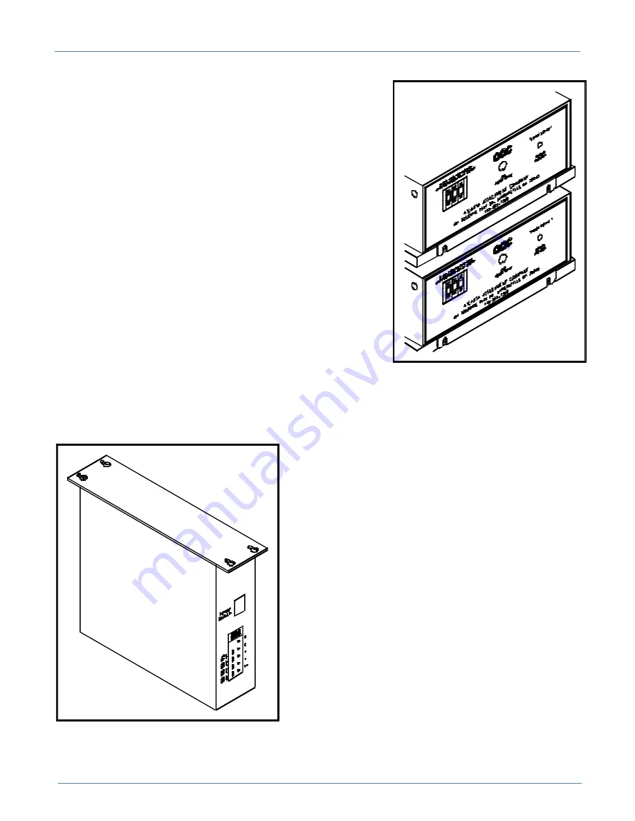
Fig. 4
Fig. 5
Stepper Control Boxes
There are two stepping motor boxes located under the
table. The box with the 10-turn adjustable potentiometer on the
front controls the Ruffler and the box without controls the Puller.
The Puller box has three Thumbwheels on the front
which are set to synchronize the puller to the sewing head. The
number is proportional to the stitch LENGTH and is not affected
by sewing speed.
The Ruffler box has three Thumbwheels on the front
which are set to synchronize the Ruffler to the sewing head. The
number is proportional to the stitch LENGTH and is not affected
by sewing speed. The 10-turn potentiometer is used to set the
speed of the Ruffler during the feed in to pleat and feed out to
make the next ruffle. It is set to maximum and is locked in place
by a small locking lever. Unlock to adjust.
Each box has its own on/off switch on the back where the
power cord plugs in. Leave this switch on all the time.
Note: The on/off switch only switches one line and
does not make the box safe to work on. Always disconnect
the main power cord before servicing the control box.
Efka Control Boxes
The sewing machine is powered by the Efka motor controller located under the table. It has its
own on/off switch which should be left on at all times. It also has some small buttons and LED's on the
front to indicate the enabled functions. The only LED that should be on is the second to last from the
bottom which sets the control to stop the machine needle
down at neutral treadle and needle up after full heal back.
The functions can be changed upon power up or after a
full heal back. The control box has been preprogrammed
to operate with the Ruffler. If the box were replaced, the
new box would need to be programmed according to the
included parameter list in order to function properly.
Notice that the sewing head does not stop at normal
needle up (lockstitch heads) position after full heal back,
but stops at needle top dead center to allow more room for
loading thicker material (the head actually turns in reverse
for a moment).
Summary of Contents for 1335M
Page 2: ......
Page 23: ...Manual Parts Lists Technical 17 Parameter Settings for Efka Controller ...
Page 24: ...Technical Manual Parts Lists 18 1335M Folder Spacer Reference Chart ...
Page 54: ...Technical Manual Parts Lists 48 ...
Page 56: ...Technical Manual Parts Lists 50 ...
Page 58: ...Technical Manual Parts Lists 52 ...
Page 60: ...Technical Manual Parts Lists 54 ...
Page 62: ...Technical Manual Parts Lists 56 ...
Page 71: ...Manual Parts Lists Technical 65 1335M 2400 Ball Screw and Nut Assembly 9000982 ...
Page 76: ...Technical Manual Parts Lists 70 ...
Page 78: ...Technical Manual Parts Lists 72 ...
Page 88: ...Technical Manual Parts Lists 82 ...
Page 90: ...Technical Manual Parts Lists 84 ...
Page 92: ...Technical Manual Parts Lists 86 ...
Page 96: ...Technical Manual Parts Lists 90 ...
Page 98: ...Technical Manual Parts Lists 92 ...
Page 100: ...Technical Manual Parts Lists 94 1335M PD Pneumatic Diagram 125618C ...
Page 101: ...Manual Parts Lists Technical 95 1335M PDK5 Pneumatic Diagram 125669C ...
Page 102: ...Technical Manual Parts Lists 96 1959 PD Pneumatic Diagram Flanging Unit 125492C ...
Page 103: ...Manual Parts Lists Technical 97 1335M 500WD Wiring Diagram Control Box 125615C ...
Page 104: ...Technical Manual Parts Lists 98 1335M WD Wiring Diagram 125619C ...
Page 105: ...Manual Parts Lists Technical 99 1335M 01WD Wiring Diagram 125629C ...
Page 106: ...Technical Manual Parts Lists 100 1334S 01WD Wiring Diagram Flanging Unit 125627C ...
Page 107: ...Manual Parts Lists Technical 101 ...


