background image


15 

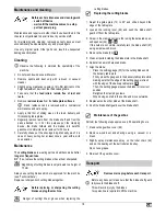
Electrical safety 


ƒ


Extension cable

 to be designed in compliance with IEC 60 

245 (H 07 RN-F) having a core cross-section of at least: 


1.5 mm² for cable lengths 

up to

 25 m 


2.5 mm² for cable lengths 

over

 25m 

ƒ


Long and thin connection lines result in a potential drop. The 
motor does not reach any longer its maximal power; the 
function of the device is reduced. 

ƒ


Plugs

 and 

coupler outlets

 on connection cables must be 

made of rubber, non-rigid PVC or other thermoplastic 
material of same mechanical stability or be covered with this 
material. 

ƒ


Protect yourself against an 

electric shock

. Avoid touching 

earthed parts with your body. 

ƒ


The connector of the connection cable must be 

splash-

proof.


ƒ


Wind off completely the cable when using a cable drum. 

ƒ


Do not use the 

cable

 for purposes for which it is not meant. 

Protect

 the cable against 

heat, oil and sharp edges

. Do 

not use the cable to pull the plug from the socket. 

ƒ


Regularly check the cable and if damaged, have it 
renewed

 by a recognised skilled electrician. 

ƒ


When running the 

connection line

 observe that it does not 

interfere, is not squeezed, bended and the plug connection 
does not get wet. 

ƒ


Regularly check the 

extension cables

 and replace them if 

they are damaged. 

ƒ


Do not use

 any defective connection cables.


ƒ


Do not set up any provisional

 electrical connections. 

ƒ


Never bypass

 protective devices or deactivate them. 

ƒ


Only hook up the machine by means of a 

fault-current 

circuit breaker

 (30 mA). 


The 

electrical connection or repairs 

to electrical parts of 

the machine must be carried out by a 

certified 

electrician 

or one of our customer service points. Local regulations – 
especially regarding protective measures – must be 
observed. 


Repairs 

to other parts of the machine must be carried out 

by the manufacturer or one of his customer service points. 


Use only original spare parts and accessory parts.


Accidents can arise for the user through the 

use of other 

spare parts

. The manufacturer is not liable for any 

damage or injury resulting from such action. 


Before the first start-up 


To achieve flawless functioning of the machine, please 
follow the instructions listed: 


ƒ


Place the 

surface planing and thicknessing machine

 at a 

location which meets following conditions: 


secured against slipping 


free of vibrations 


even 


free of tripping hazards 


adequate light 

ƒ


Before each use

, check 


Connection cables 

for defects (cracks, cuts, etc.). 

 Do not use any defective cables. 


whether the 

pushstick 

is to hand 


Is the unused blade shaft covered by the blade shaft 
guard?  

ƒ


When working do not stand directly in front or behind the 
machine but stand to the side. 


You have to attach the following parts: 


Base frame


A1 

-

 A7


ƒ


Assemble the four parts of the stand as shown in the figures 
A1 through A7. 

ƒ


Use a second person to place the surface planing and 
thicknessing machine on the stand. 

ƒ


Secure the surface planing and thicknessing machine to the 
stand. 


Securing on the floor


A8


Secure the surface planing and thicknessing machine to the 
floor using 4 screws. 


Guide plate 


ƒ


Secure the guide plate guideway (7) to the housing. 

ƒ


Slide in the guide plate holder (10) and secure the locking 
lever (12). 

ƒ


Mount the guide plate (13). 


Shavings exhauster


C1 

-

 C7


ƒ


Install the shavings exhauster connector (16). 

ƒ


Connect the shavings exhauster hose (17) and secure it 
using a hose band clip (18). 

ƒ


Connect the shavings exhauster hood (27) to the exhaust 
hose and tighten the hose band clip. 

ƒ


Attach the shavings bag (19) to the exhauster connector and 
secure it using the hose band clip. 


Start-up 


Mains connection 
Compare the voltage listed on the machine’s type plate, e.g. 
230 V, with the mains voltage and connect the machine to a 
suited and properly earthed electrical socket. 


Alternating current motor: 
Use a shockproof plug, mains voltage 230 V with residual 
current circuit breaker and 10 A inert fuses. 

ƒ


Use connection cable or extension cable respectively with a 
cross section of at least 1.5 mm². 


Summary of Contents for ADH 254 A -

Page 1: ... planing and thicknessing machine Operating Manual Safety instructions Spare parts Page 12 Dégauchisseuse raboteuse Instructions d utilisation Consignes de sécurité Pièces de rechange Page 23 Vlak en vandiktebank Bedieningshandleiding Veiligheidsinstructies Reserveonderdelen Blz 34 ADH 254 A ...

Page 2: ...sation pour tout utilisateur futur U mag het apparaat niet in bedrijf nemen voordat U deze bedieningsaanwijzing heeft gelezen alle instructies hebt gevolgd en het apparaat volgens de beschrijving heeft gemonteerd Bewaar deze bedieningsaanwijzing voor alle toekomstige toepassingen Elektrische Geräte gehören nicht in den Hausmüll Geräte Zubehör und Verpackung einer umwelt freundlichen Wiederverwertu...

Page 3: ...llständigkeit evtl Transportschäden Teilen Sie Beanstandungen umgehend dem Händler Zulieferer bzw Hersteller mit Spätere Reklamationen werden nicht aner kannt Geräuschkennwerte EN ISO 3744 Einsatz der Maschine als Abricht und Dickenhobel mit serienmäßigen Hobelmessern Schalleistungspegel Schalldruckpegel am Arbeitsplatz Leerlauf LWA 109 5 dB A LpA 93 9 dB A Bearbeitung Abrichten LWA 112 3 dB A LpA...

Page 4: ...Regen ausgesetzt werden Metallteile Nägel etc sind aus dem zu hobelnden Material unbedingt zu entfernen Restrisiken Auch bei bestimmungsgemäßer Verwendung können trotz Ein haltung aller einschlägigen Sicherheitsbestimmungen aufgrund der durch den Verwendungszweck bestimmten Konstruktion noch Restrisiken bestehen Restrisiken können minimiert werden wenn die Sicherheitshin weise und die Bestimmungsg...

Page 5: ... darauf dass das Werkstück keine Kabel Seile Schnüre oder ähnliches enthält Bearbeiten Sie kein Holz das zahlreiche Asteinschlüsse oder Astlöcher enthält Beginnen Sie mit dem Hobeln erst wenn die Schneidwalze ihre erforderliche Drehzahl erreicht hat Verwenden Sie nur scharfe Hobelmesser da stumpfe Hobelmesser nicht nur die Rückschlaggefahr erhöhen sondern auch den Motor belasten Verwenden Sie zum ...

Page 6: ...Der Elektroanschluss bzw Reparaturen an elektrischen Teilen der Maschine hat durch eine konzessionierte Elektrofachkraft oder einer unserer Kundendienststellen zu erfolgen Örtliche Vorschriften insbesondere hinsichtlich der Schutzmaßnahmen sind zu beachten Reparaturen an anderen Teilen der Maschine haben durch den Hersteller bzw einer seiner Kundendienststellen zu erfolgen Nur Originalersatz und Z...

Page 7: ...its schädlich Schließen Sie deshalb immer den Spänesack 19 an den Absauganschluss 16 an C6 C7 L leeren Sie den Spänesack regelmäßig L Der Motor läuft nur wenn die Absaughaube 27 ordnungsgemäß angebracht wurde und dadurch den Sicherheitsschalter auslöst Arbeiten mit dem Abricht und Dickenhobel Vor Arbeitsbeginn beachten Sie die folgenden Sicherheitshinweise um das Verletzungsrisiko so gering wie mö...

Page 8: ...chlag an 2 Lösen Sie die Feststellklemme für die Messerschutzabdeckung 46 3 Durch Drehen der Einstellschraube 30 können Sie den Arm der Messerschutzabdeckung einstellen 4 Bei flachen Werkstücken 75 mm Schieben Sie die Messerschutzabdeckung 23 bis an den Führungsanschlag 13 heran und heben Sie sie entsprechend der Werkstückdicke an Drehen sie dazu die Einstellschraube 30 Schieben Sie das Werkstück ...

Page 9: ...rät ausschalten Stillstand der Maschine abwarten Netzstecker ziehen Weitergehende Wartungs und Reinigungsarbeiten als die in diesem Kapitel beschrieben dürfen nur vom Kundendienst durchgeführt werden Zum Warten und Reinigen entfernte Sicherheitseinrichtungen müssen unbedingt wieder ordnungsgemäß angebracht und überprüft werden Nur Originalteile verwenden Andere Teile können zu unvorhersehbaren Sch...

Page 10: ...schrauben wieder fest Gehen Sie dabei von innen nach außen vor 8 Wechseln Sie auch das andere Messer der Schneidwalze aus 9 Schieben Sie die Messerschutzabdeckung wieder über die Schneidwalze Wartung des Getriebes Führen Sie folgendes ca alle 50 Betriebsstunden durch 1 Nehmen Sie die Getriebeabdeckung 48 ab 2 Entfernen Sie Holzstaub und Späne mit Hilfe eines Staubsaugers oder eines Pinsels 3 Behan...

Page 11: ...he Beseitigung Maschine läuft nach Einschalten nicht an oder schaltet während des Leerlaufs selbsttätig ab Stromausfall Verlängerungskabel defekt Motor oder Schalter defekt Sicherung überprüfen Kabel überprüfen defekte Kabel nicht mehr benutzen Motor oder Schalter von einer konzessionierten Elektrofachkraft überprüfen oder reparieren lassen bzw durch Originalersatzteile ersetzen lassen Maschine bl...

Page 12: ...hraube mit Vierkantansatz 35 Hebel für Dickenhobeleinstellung 9 Innensechskantschraube M 8 x 20 36 Sicherheitsaufkleber 363742 10 Anschlagträger 37 Innensechskantschlüssel SW 6 11 Distanzplatte 38 Innensechskantschlüssel SW 5 12 Feststellhebel für Anschlagträger 39 Innensechskantschlüssel SW 4 13 Führungsanschlag 363862 40 Skala für Winkelverstellung 14 Flachrundschraube mit Vierkantansatz 41 Antr...

Page 13: ...erkstückbreite max 254 mm Werkstückhöhe beim Dickenhobeln 5 160 mm Schnitttiefe Abrichthobeln 0 3 mm Schnitttiefe Dickenhobeln 0 2 mm Abmessungen der Hobelmesser Länge x Breite x Dicke 258 x 20 x 2 5 mm Tischgröße Abrichthobel 1050 x 260 mm Dickenhobel 480 x 254 mm Tischhöhe mit Untergestell 890 mm Gewicht ca 82 kg Absauganschluss 75 mm Zum Absaugen können handelsübliche Kleinentstauber oder Indus...

Page 14: ... the contents of the box That it is complete Check for possible transport damage Report any damage or missing items to your dealer supplier or the manufacturer immediately Complaints made at a later date will not be acknowledged Characteristics noise values EN ISO 3744 Machine used as surface planer and thicknesser with standard cutting blades Noise power level Sound pressure level at the workplac...

Page 15: ...nconditionally to be removed from the material to be planed or thicknessed Residual risks Even if used properly residual risks can exist even if the relevant safety regulations are complied with due to the design determined by the intended purpose Residual risks can be minimised if the Safety instructions and the Normal intended use as well as the whole of the operating instructions are observed O...

Page 16: ...es increase not only the risk of backstrokes but also charge the motor Use appropriate devices when machining thin work pieces to position and guide the wood pieces properly When machining make sure that the unused blade shaft is covered by the knife guard Do only use tools according to EN 847 1 which are marked with MAN The use of other tools and other accessories can signify a risk of injury for...

Page 17: ...ts Accidents can arise for the user through the use of other spare parts The manufacturer is not liable for any damage or injury resulting from such action Before the first start up To achieve flawless functioning of the machine please follow the instructions listed Place the surface planing and thicknessing machine at a location which meets following conditions secured against slipping free of vi...

Page 18: ...n and installed the machine as described Also note the following important points Make sure that the non used area of the blade shaft is covered by the blade shaft guard Place yourself outside of the area of danger Place your hands flat on the workpiece with fingers closed Never remove loose splinters chips or similar by hand Connect the shavings bag Make sure that the feed rollers and cutting too...

Page 19: ...the guide plate and the delivery table plate Push the workpiece with your closed right hand over the feed table plate 4 Turn the machine off if the work is not immediately continued Thicknessing The purpose of thicknessing is to make the workpiece with already planed surface thinner For this the workpiece is guided through the machine and machined on its top surface The already planed surface face...

Page 20: ...se cutting blades which are approved for the machine see Technical data Replace or sharpen both cutting blades together Before replacing or sharpening the cutting blades unplug the machine Danger of cutting Wear gloves when replacing the cutting blades Replacing the cutting blades 1 Adjust the guide plate 13 to 90 and slide it beyond the edge of the table plate 2 Loosen the locking lever 46 and pu...

Page 21: ...utting blades the draw in out rollers 50 51 G5 the feed and delivery tables Check for damages and have it replaced by an electrician if required The grippers must fall back automatically and the tips must not be rounded The cutting blades must be sharp and properly secured Check that the coating shows no damages and that the workpieces are conveyed without problems Apply a thin film of sliding wax...

Page 22: ...e 42 Driving belt 16 Exhaust neck 363889 43 Driving belt 17 Extraction hose 363895 44 Roller chain 363892 18 Hose clip 363893 45 Depth of cut scale 363891 19 Shavings bag 363890 46 Clamping device 363882 20 Motor protection switch 47 Blade shaft 363908 21 EMERGENCY STOP button 48 Gearbox cover 363864 22 ON OFF switch 49 Backstroke protection 363881 23 Blade shaft guard 363888 50 Draw in roller 24 ...

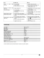
Page 23: ...direction Machine the workpiece in multiple passes Workpiece advance is slow during thicknessing Thicknessing adjusting lever not in its top position Resin on the thicknessing table plate Sluggish transport rollers Put the thicknessing adjusting lever to its top position F2 Clean the table plate and apply a thin film of sliding wax Repair the transport rollers Technical data Type Model MBY10 ADH 2...

Page 24: ...sence éventuelle de dommages dus au transport Informez immédiatement le revendeur le transporteur et ou le fabricant en cas de réclamation Sachez que les réclamations ultérieures ne sont plus acceptées Émissions sonores EN ISO 3744 Utilisation de la machine comme dégauchisseuse raboteuse avec des lames de rabot de série Niveau de conductibilité acoustique Niveau de pression acoustique á la place d...

Page 25: ...t à l usager Le fabricant décline toute responsabilité pour les dommages de tout type résultant de modifications non autorisées de la dégauchisseuse raboteuse effectuées par l utilisateur Seule les personnes maîtrisant la machine et ayant reçu les instructions adéquates concernant les dangers sont autorisées à équiper utiliser et entretenir la dégauchisseuse raboteuse Les travaux d entretien doive...

Page 26: ...câble ou l appareil Tenir à l écart de votre plan de travail toute personne étrangère Ne surchargez pas la machine Elle fonctionne mieux et avec une sécurité accrue dans la plage indiquée Veillez au montage complet et correct des équipements de sécurité pendant l exploitation et ne modifiez rien sur la machine qui risquerait d influencer sa sécurité Il est nécessaire de se placer en bonne position...

Page 27: ...it être protégé contre les projections d eau En cas d utilisation d un tambour dérouler le câble complètement N employez pas le câble à des fins pour lesquelles il n est pas prévu Protégez le câble de la chaleur l huile et des arêtes tranchantes Ne tirez pas sur le câble pour retirer la fiche de la prise au secteur Contrôlez régulièrement le câble et demandez à un spécialiste électricien de le rem...

Page 28: ...machine en service appuyer de nouveau sur le bouton rouge Arrêt Appuyer sur le bouton rouge 0 Interrupteur ARRET D URGENCE En cas d urgence la dégauchisseuse raboteuse peut être arrêtée en actionnant le bouton poussoir ARRET D URGENCE 21 Protection du moteur Le moteur est équipé d un disjoncteur de protection et s arrête automatiquement en cas de surcharge Une remise en marche du moteur est possib...

Page 29: ...rer à nouveau le levier de blocage 12 Réglage de la profondeur de rabotage E9 1 Tourner la vis de réglage pour la profondeur de coupe 29 2 La profondeur de coupe est indiquée sur l échelle graduée pour le réglage de la profondeur de coupe 45 Réglage du capot de protection des lames E10 E12 1 Placer la pièce contre le butoir de guidage 2 Desserrer le dispositif de fixation du capot de protection de...

Page 30: ...r l équipement Attendre l arrêt complet de la machine retirer la fiche du secteur Les autres interventions d entretien et de réparation qui ne sont pas décrites dans ce chapitre doivent être effectuées uniquement par le S A V Les dispositifs de sécurité enlevés pour effectuer des interventions de maintenance ou de nettoyage doivent impérativement être remontés et vérifiés N utiliser que des pièces...

Page 31: ... les vis de blocage Travailler de l intérieur vers l extérieur 8 Remplacer également l autre lame du cylindre de coupe 9 Remettre le capot de protection des lames au dessus du cylindre de coupe Entretien de l engrenage Effectuer les démarches suivantes env toutes les 50 heures de service 1 Enlever le couvercle de l engrenage 48 2 Enlever les poussières et copeaux de bois à l aide d un aspirateur o...

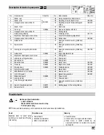
Page 32: ...ignation Réf de commande Ref Désignation Réf de commande 1 Bâti face arrière 20 Disjoncteur moteur 2 Bâti face latérale 21 Interrupteur ARRET D URGENCE 3 Vis à six pans creux M6 x 10 22 Interrupteur marche arrêt 4 Bâti face avant 363902 23 Capot de protection des lames 363888 5 Outils compl 363884 24 Volant de blocage 6 Vis à six pans creux M8 x 16 25 Manivelle de réglage de hauteur 7 Plateau de g...

Page 33: ...ine s arrête pendant le processus de rabotage Lame de rabot émoussée Avance de coupe trop importante Disjoncteur protecteur du moteur s est déclenché Remplacer ou aiguiser la lame Travailler à une vitesse d avancement moins élevée Remettez le moteur en marche après son refroidissement Protection du moteur page 9 Pièce reste coincée pendant le rabotage Profondeur de coupe trop élevée Réduire la pro...

Page 34: ...x de la pièce 254 mm Hauteur de la pièce pour le rabotage 5 160 mm Profondeur de coupe pour le dégauchissage 0 3 mm Profondeur de coupe pour le rabotage 0 2 mm Dimensions des lames de rabot Longueur x largeur x épaisseur 258 x 20 x 2 5 mm Taille de la table Dégauchisseuse 1050 x 260 mm Raboteuse 480 x 254 mm Hauteur du plateau avec bâti 890 mm Poids environ 82 kg Raccord d aspiration Aspiration ut...

Page 35: ... verpakking op Aanwezigheid van alle onderdelen Eventuele transportschade In het geval van onvolkomenheden dit direct aan uw leverancier melden Latere reclamaties worden niet in behandeling genomen Geluidskenmerken EN ISO 3744 Toepassing van de machine als vlak en vandiktebank met standaard schaafmessen Geluidsvermogen Geluidsdrukpegel bij het werk Onbelast LWA 109 5 dB A LpA 93 9 dB A Belast Vlak...

Page 36: ...n onderdelen spijkers etc moeten absoluut uit het te schaven materiaal verwijderd worden Restrisico s Ook bij het gebruik volgens de voorschriften zijn er op grond van de constructie voor de toepassing van deze machine nog een aantal restricties De restricties kunnen geminimaliseerd worden wanneer de veiligheids gebruiks gezondheid en onderhoudsvoorschriften nauwkeurig in acht genomen worden Consi...

Page 37: ...en niet alleen het terugslaggevaar verhogen maar ook de motor belasten Gebruik voor het schaven van dunne werkstukken voorzieningen om de stukken hout in positie te brengen en te verplaatsen Let er bij het schaven op dat de niet gebruikte snijrol door de mesafdekking wordt afgedekt Gebruik alleen gereedschap dat aan de norm NEN EN 847 1 voldoet en met MAN gekenmerkt is Het gebruik van gereedschapp...

Page 38: ...en of reparaties mogen alleen door een erkend bedrijf of een erkende reparatiewerkplaats uitgevoerd worden De plaatselijke voorschriften moeten opgevolgd worden Reparaties aan andere delen van de machine mogen alleen door de fabrikant of een door hem erkende werkplaats uitgevoerd worden Alleen de originele toebehoren en onderdelen gebruiken Bij het gebruik van niet originele onderdelen kunnen risi...

Page 39: ...an de werkzaamheden dient u de volgende punten in acht te nemen om de kans op verwondingen zo laag mogelijk te houden Werkplek opgeruimd Staat de vlak en vandiktebank stabiel Zijn alle bevestigingsschroeven goed vastgedraaid Zijn de messen correct op de snijrol bevestigd Is de duwstok binnen handbereik U mag het apparaat niet gebruiken voordat u deze bedieningshandleidning heeft gelezen alle voors...

Page 40: ...en eerst op het afnametafelblad druk op het werkstuk uit 7 Schakel de machine uit als u niet meteen verder werkt Aanschuinen E16 1 Leg het werkstuk tegen de schuin geplaatste aanslag 2 Stel de mesafdekking zodanig in dat ze het werkstuk net raakt 3 Druk het werkstuk met uw linkerhand met een gesloten vuist tegen de aanslag en het afnametafelblad Schuif het werkstuk met uw gesloten rechterhand over...

Page 41: ...stofzak bij sterke verontreiniging of minstens eenmaal per jaar met de hand in mild zeepsop Onderhoud De schaafmessen zijn onderhevig aan slijtage en worden na langdurig of regelmatig gebruik stomp Vervang in dat geval de schaafmessen of laat ze slijpen De schaafmessen mogen slechts tot een hoogte van 15 mm nageslepen worden Gebruik alleen schaafmessen die geschikt zijn voor de machine zie Technis...

Page 42: ...g met de ingesloten garantieverklaring Onderhouds en reinigingsschema Vóór elke inbedrijfstelling Controleer de aansluitkabels de terugslagbeveiliging 49 G5 de schaafmessen in en uittrekwals 50 51 G5 de opname en uitlooptafel Op beschadigingen controleren en desgewenst door een elektricien laten vervangen De grijpers moeten automatisch terugvallen en de uiteinden mogen niet afgerond zijn De schaaf...

Page 43: ... Afzuigslang 363895 44 Rollenketting 363908 18 Klem 363893 45 Snijdiepteschaal 363864 19 Spaanzak 363890 46 Kleminrichting 363881 20 Motorveiligheidsschakelaar 47 Messenwals 21 NOOD UIT schakelaar 48 Drijfwerkafdekking 22 In uitschakelaar 49 Terugslagbeveiliging 23 Mesafdekking 363888 50 Intrekwals 24 Vastzetwiel 51 Uittrekwals 25 Slinger voor hoogte instelling 52 Inbussleutel SW 3 26 Schaal voor ...

Page 44: ...eschaafd Werkstuk vanuit de tegenovergestelde richting bewerken Werkstuk in meerdere fasen bewerken Te geringe werkstukaanvoer bij het vandikteschaven Hendel voor vandiktebankinstelling niet in de bovenste positie Hars op het vlaktafelblad Transportrollen stroef Zet de hendel voor de vandiktebankinstelling in de bovenste positie F2 Tafelblad reinigen en met een dunne laag skiwax behandelen Transpo...

Page 45: ...363860 00 07 08 ATIKA GmbH Co KG Schinkelstraße 97 59227 Ahlen Postfach 21 64 59209 Ahlen Germany Tel 0 23 82 8 92 0 Fax 0 23 82 8 18 12 E mail info atika de Internet www atika de ...

Reviews: