PAGE
100
ALMAC s.r.l.
The levelling speeds are significantly reduced compared to those with the
machine in the transport position.
This is wanted both to make the manoeuvre comfortable for the operators and
to minimise the effects due to inertia.
This additional system is not required by standard UNI EN 280:2015
because it would be enough to have the normal frame inclination control made
in performance level D as required in section 5.3.2.3 of the same standard.
This additional safety system is described in paragraph 3.4.2 "Redundant frame
inclination and height control device"
Preliminary notes:
-
The system is active only when the platform floor is higher than 2mt
-
The system is active only within 3° of inclination
-
The system is active only if the work platform is below the maximum
travel height of 4.5 mt platform floor (scissor frame angle with respect to
frame 23°)
-
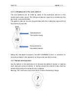
If indicator light 1 is off, it means that the inclination is less than 0.5°
-
If indicator light 1 is flashing, it means that the inclination is greater than
0.5° and less than 3°
Summary of Contents for 850-BL EVO
Page 7: ...PAGE 7 ALMAC s r l MAXIMUM WORKING HEIGHT TRAVELLING NOT PERMITTED H1 H2 G3 H3 H4 G4 G1 L1 G2 ...
Page 10: ...PAGE 10 ALMAC s r l ...
Page 23: ...PAGE 23 ALMAC s r l ...
Page 49: ...PAGE 49 ALMAC s r l 35 Combustion engine 36 Fuel tank 37 Bi levelling chassis 37 38 ...
Page 78: ...PAGE 78 ALMAC s r l ...
Page 80: ...PAGE 80 ALMAC s r l ...
Page 144: ...PAGE 144 ALMAC s r l ...
Page 145: ...PAGE 145 ALMAC s r l ...
Page 146: ...PAGE 146 ALMAC s r l ...
Page 147: ...PAGE 147 ALMAC s r l ...
Page 148: ...PAGE 148 ALMAC s r l ...
Page 149: ...PAGE 149 ALMAC s r l ...
Page 150: ...PAGE 150 ALMAC s r l ...
Page 151: ...PAGE 151 ALMAC s r l ...
Page 152: ...PAGE 152 ALMAC s r l ...
Page 159: ...PAGE 159 ALMAC s r l ...
Page 162: ...PAGE 162 ALMAC s r l 8 ATTACHMENTS 8 1 Declaration of conformity ...
Page 164: ...PAGE 164 ALMAC s r l MANDATORY ROUTINE INSPECTIONS Date Observations Seal Signature ...
Page 178: ...PAGE 178 ALMAC s r l 8 4 Hydraulic diagram See attachment 8 5 Wiring diagram See attachment ...


