background image

ATECPOOL SIROCCO HEAT PUMP > User Manual

9

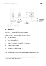
e. Items need to be checked during running test:

● During the first running, check if unit current is normal or not;
● Check if each function button on control panel are functioning correctly or not;
● Display screen is correct or not;
● Is there any leakage in the whole heating circulation system?
● Condensation drain is correct or not;
● Are there any abnormal sounds or vibration while running the unit?

2. Control Function Description

2.1 Operation Description

Controller Operation Description (Subject to specific model)

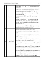
Control Panel Diagram
Summary of Contents for SIROCCO AIHP115

Page 1: ...O HEAT PUMP User Manual SIROCCO INVERTER HEAT PUMP Models AIHP115 AIHP180 AIHP212 AIHP253 FULL DC INVERTER SWIMMING POOL HEAT PUMP USER MANUAL Please read this manual carefully before using and keep it in a safe place ...

Page 2: ...ATECPOOL SIROCCO HEAT PUMP User Manual ...

Page 3: ...rameters 1 II System Specification 2 1 Specification 2 2 Unit Dimensions 3 3 Exploded View 4 III Installation Instructions 5 IV Running Test 8 1 Inspection Before Running Test 8 2 Control Function Description 9 3 Fault Code and Solution 13 V WIFI Settings 17 ...

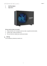
Page 4: ...rance Please read the below instructions Please install the unit in compliance with local laws regulations and standards Confirm power voltage and frequency The unit should be installed by a professional installer Warning To be installed by professional installer only ...

Page 5: ... 2 90 0 69 4 53 0 75 5 36 0 88 5 98 EER 4 25 1 98 4 08 1 83 4 01 1 79 4 09 1 78 Power supply 220 240V 50 60Hz 380 415V 3N 50 60Hz Max Input power kW 1 9 2 3 5 4 6 5 Max current A 13 7 20 9 10 5 12 5 Heating temperature range 27 C 34 C Cooling temperature range 26 C 15 C Running temperature range 10 C 48 C Refrigerant R410A Compressor MITSUBISHI ELECTRIC DC inverter Air side heat exchanger Hydrophi...

Page 6: ...ATECPOOL SIROCCO HEAT PUMP User Manual 3 2 Unit Dimensions Model A B C D F G AIHP115 980 660 666 399 380 97 AIHP180 AIHP212 1125 765 655 455 450 97 AIHP253 ...

Page 7: ...t plate 17 Top cover 2 Fan 10 Handle 18 Electrical box cover 3 Motor 11 controller display 19 Electrical box 4 Motor support 12 EEV component 20 Left plate 5 Right plate 13 Middle plate 6 Compressor 14 Evaporator 7 Four way valve 15 Back plate 8 Titanium heat exchanger 16 Pillar ...

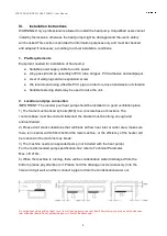
Page 8: ...p should be installed in a good ventilation place 1 The frame must be fixed by bolts M10 to a concrete base or brackets The concrete base must be solid and fastened the bracket must be strong enough and antirust treated 2 Please don t stack substances that will block air flow near inlet or outlet area make sure there is no barrier within 50cm behind the main machine or the efficiency of the heater...

Page 9: ... is placed after the water pump and filtration The by pass path usually consists of 3 valves That makes it possible to adjust water flow which passes through the heat pump and isolates the heat pump completely from any maintenance without affecting flow of filtration cycle The filter must be cleaned regularly to ensure that the water in the system is clean and avoids blocking the filter It is nece...

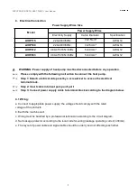
Page 10: ...t the heat pump Step 1 Detach electrical side panel by a screwdriver to access the electrical terminal block Step 2 Insert cable into heat pump unit port Step 3 Connect power supply cable to terminal block according to the diagram below 4 1 Wiring a Connect to appropriate power supply the voltage should comply with the rated voltage of the products b Earth the machine well c Wiring must be handled...

Page 11: ...e Correct piping and wiring Air inlet and outlet ports from the air unit unblocked Drainage and venting are unblocked and no water leaking Leakage protector is working Piping insulation is working Ground wire is connected correctly c All wiring and piping should be connected well and carefully checked then fill the water tank with water before power is switched on d Empty all air within pipes and ...

Page 12: ...on control panel are functioning correctly or not Display screen is correct or not Is there any leakage in the whole heating circulation system Condensation drain is correct or not Are there any abnormal sounds or vibration while running the unit 2 Control Function Description 2 1 Operation Description Controller Operation Description Subject to specific model Control Panel Diagram ...

Page 13: ...rface press and hold the key for 3 seconds to turn on off 3 Check Running Parameters In the main interface press and hold the key for 3 seconds to enter the unit status parameter query use the and keys for parameter browsing and press the key to exit the parameter query See table 1 4 Choose Mode In the power on state long press for 3 seconds to switch to working mode heating mode and cooling mode ...

Page 14: ...y After setting the minute value press again to finish 8 Adjust Timing Press for 3 seconds to enter the timing setting Enter timing selection when the clock flashes timing on 1 use and to set times Click again to change to the clock and can set minutes Click again to change Set Timing Off 1 The clock flashes showing Hour and press Key C and Click again to change to clock minute use to set minutes ...

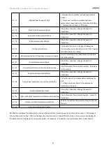
Page 15: ...he electric heater function Table 1 Code Meanings Display Range A01 Water inlet temperature 30 99 A02 Water outlet temperature 30 99 A03 Ambient temperature 30 99 A04 Exhaust temperature 0 125 A05 Air inlet temperature 30 99 A06 Outer coil temperature 30 99 A07 Inner coil temperature 30 99 A08 Main EEV opening A09 EEV opening EVI A10 Compressor current A11 IPM temperature A12 DC bus voltage value ...

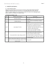
Page 16: ...g Water pump will run automatically for first grade antifreeze Er 05 High pressure Protection Measure the pressure value when the heat pump is heating cooling If it s higher than 44 0 bar itmeans heat pump has got high pressure protection 1 Detect EEV step low pressure and suction temp 2 Detect the inlet outlet water temp 3 Check for air in the refrigeration system 4 Clean the water exchanger or w...

Page 17: ...sary Er 23 Low outlet water temp protection when cooling Check the water flow and water system fix replace it if necessary Er 27 Water outlet temperature failure Check the connection change the sensor if necessary Er 28 Compressor transformer over current protection 1 Wait for about 3 5 minutes before restarting the unit 2 Change the driver board if the compressor transformer is broken Er 29 Sucti...

Page 18: ...oller and inverter module 258 AC input phase loss Input phase loss available for three phase module Check the input circuit 260 AC input over current Input three phase unbalance available for three phase module Check the three phase voltage 264 AC input voltage is low Input voltage is low Check the input voltage 272 High pressure failure Compressor high voltage failure reservation 288 IPM temp too...

Page 19: ... ended 2 Water temperature of the unit does not reach the water temperature needed to start up 1 Please wait patiently for the end of protection time 2 Wait for water temperature to reach the level needed Unit is running normally but hot water temperature is low 1 Improper temperature setting 2 Large hot water consumption 3 Air inlet port or outlet port of outdoor machine or indoor machine is bloc...

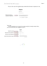
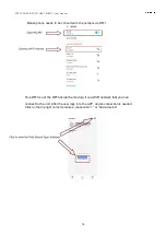
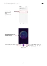
Page 20: ...enter the WI FI network When entering the icon will flash fast for 3 seconds and then flash slowly App Download Search Smart Life Start the software After the installation is complete tap the icon to start the software Smart Life User registration The first time you use Smart Life software you need to register your user ...

Page 21: ...nual 18 When an user enters the registration page please follow the steps to register your user User Login Once the registration is successful the software will jump to the login screen Enter the correct user name and password to log in ...

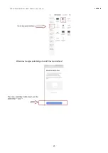
Page 22: ... be connected to the network via WIFI This WIFI is not the WIFI inside the module it is a WIFI network that you can connect to the unit After the user logs in to the APP device connection is needed Click on the top right corner to make a connection or Add a device ...

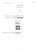
Page 23: ...ATECPOOL SIROCCO HEAT PUMP User Manual 20 When device type selected go to add device interface ...

Page 24: ...ATECPOOL SIROCCO HEAT PUMP User Manual 21 ...

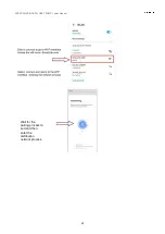
Page 25: ...ATECPOOL SIROCCO HEAT PUMP User Manual 22 Wait for the pairing process to end and then enter the distribution network process ...

Page 26: ...ATECPOOL SIROCCO HEAT PUMP User Manual 23 Unit successfully added showing device connected Click to enter control ...

Page 27: ...ATECPOOL SIROCCO HEAT PUMP User Manual 106 10020 017 ...

Reviews: