AT&T Digital Magic Messenger
Rear Panel Description
●
●
●
●
●
●
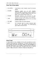
24V AC/DC
POWER
PHONE
LINE
VOLUME
AUX
3-pin power jack accepts plug from power
supply.
Switches power on or off. Caution:
Announcements are erased if switch is placed in
off position. The battery backup works only if the
power is removed while this switch is on.
Standard modular jack connects to your
telephone using modular jumper cord (supplied).
Standard modular jack connects to the incoming
modular telephone cord.
Controls volume of monitor speaker.
1/8" mini-jack used to connect external audio
source (e.g. tape player) for downloading
prerecorded announcement.
●
●
●
●
PHONE LINE
24V AC/DC
POWER
AUX
ON
OFF
VOLUME
AT&T Digital Magic Messenger
Installation
Unpacking & Inspection
The Magic Messenger was carefully checked at the factory. Inspect
the carton and unit for signs of damage. If damage is found, notify the
retailer from whom the unit was purchased. If the unit was shipped to
you, you must file a claim for damage with the shipping company.
Installation Precautions
Refer to the mounting template included with the unit for instructions
on wall-mounted installation.
Observe the following installation precautions:
Do not install the unit in damp areas, or in areas where it is likely
to be exposed to rain or moisture.
Do not install the unit in areas where the average temperature is
likely to go below 32°F or exceed 90°F.
Use suitable fasteners on hollow walls or other similar thin
materials.
If the telephone line has "call-waiting," this service must be
terminated by your phone company in order for the Magic
Messenger to operate properly.
Connecting a Power Supply
Connect the output plug from the power supply included with the
Magic Messenger into the 24V AC/DC jack on the rear panel of the
Magic Messenger. Plug the power supply into any convenient 110V
AC outlet.
Base Panel
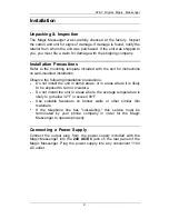
A small switch on the underside of the unit is provided to accom-
modate certain telephone configurations. This switch should be set in
the ’L’ position (loop start), the factory setting, for most installations. If
the Magic Messenger is to be installed in conjunction with a PBX sys-
tem that uses a ground start trunk, the switch must be set to the ’G’
position. (Make sure power if off when changing configurations.)
8
9
Summary of Contents for Digital Magic Messenger System
Page 16: ...AT T...


