background image


Asycube CC-Link Gateway 

User Guide 

© 

Copyright Asyril S.A. 

000.103.256 

Version : A 


13/21


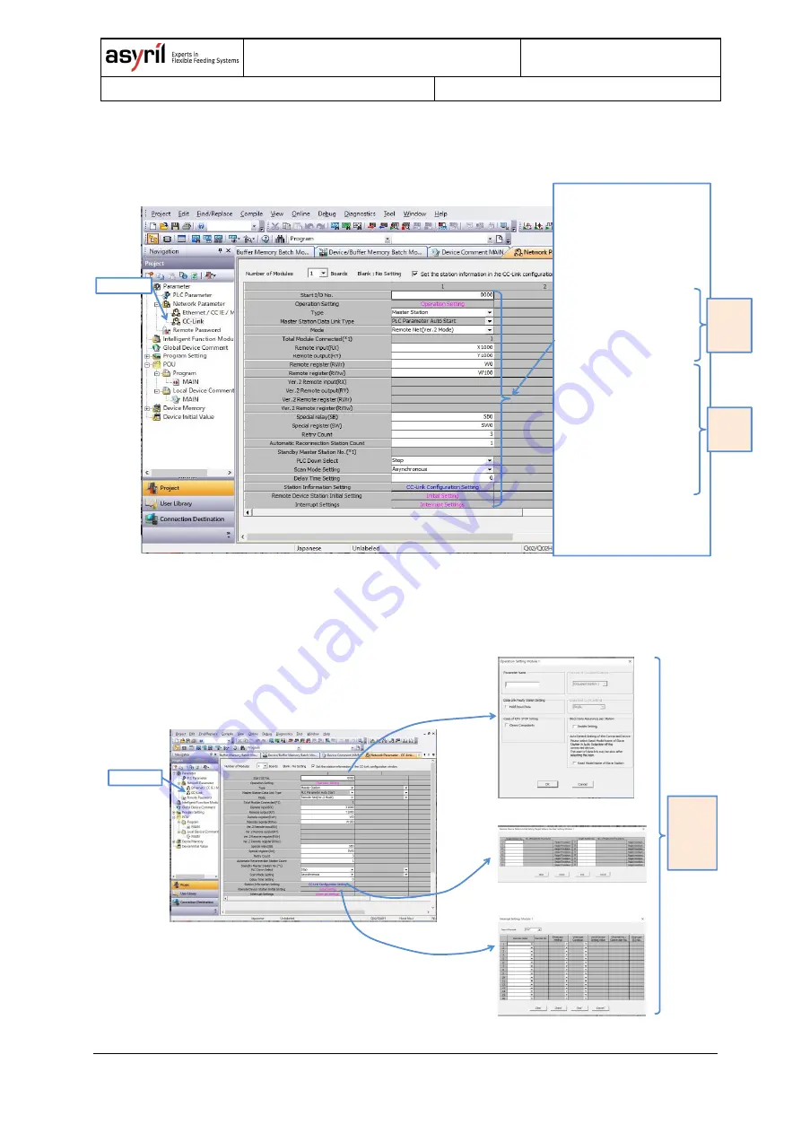
5.2.3.  CC-Link Parameter step 2 

CC-Link parameters are set by step 2 as the following figure shows. 

5.2.4.  CC-Link Parameter step 3 

CC-Link parameters are set by step 3 as the following figure shows. 


Double Click 

Double Click 

2) Operation Setting Module1 

3) Remote Device Station Initial Target  

Station Number Setting Module1 

4) Operation Setting Module1 

Default : 

No setting 

(Blank) 

1) CC-Link 

Double Click 

1) CC-Link 

2) Examples of CC-Link Parameters 


- Start I/O No. 

    0000 

- Operating Setting 

    (To be set at the next pages) 

- Type (CC-Link module in the PLC) 

   Master Station 

- Mode 

    Remote Net (Ver.2 Mode)


- Remote input (RX) 

    X1000 

- Remote output (RY) 

    Y1000 

- Remote register (RWr) 

    W0 

- Remote register (RWw) 

    W100 


 - Special relay (SB) 
   SB0 
 - Special register (SW) 
   SW0 
 - Retry Count 
   3 
 - Automatic Reconnection St Cnt 
   1 
 - PLC Down Select 
   Stop 
 - Scan Mode Setting 
   Asynchronous 
 - Delay Time Setting 
   0 
 - Station Information Setting 
   (To be set at the next pages) 
 - Remote Device St Initial Setting 
   (To be set at the next pages) 

- Interrupt Settings 

   (To be set at the next pages) 

Values 
should 
be set to 
suit a PLC 
program 

Default 
values 
of the 
PLC 
 

Summary of Contents for Asycube CC-Link Gateway

Page 1: ...Asycube CC Link Gateway User Guide Document Asyril_ASYCUBE_CC LINK_GATEWAY_User_Guide_EN 000 103 256 Version A Date 14 10 2019 ...

Page 2: ...ON 8 5 COMMISSIONING AND INTEGRATION 9 5 1 GENERAL PRINCIPLES 9 5 1 1 Import the fieldbus device description file 9 5 1 2 Add the Gateway in the configuration 9 5 1 3 Program and run the application 9 5 2 EXAMPLE FOR CC LINK ON MITSUBISHI MELSEC Q SERIES 11 5 2 1 Setting CC Link communication conditions with a PLC editor software to use the gateway 12 5 2 2 CC Link Parameter step 1 12 5 2 3 CC Lin...

Page 3: ...Asycube CC Link Gateway User Guide Copyright Asyril S A 000 103 256 Version A 3 21 ...

Page 4: ...llowing symbols are used DANGER Failure to observe the instruction may result in death or serious injury DANGER Failure to observe the instruction may result in electrocution or serious injury due to electric shock WARNING Failure to observe the instruction may result in injury or property damage NOTE The user should read carefully this information to ensure the correct use of the product although...

Page 5: ...eway Power supply 2 3 Asycube offline configuration not connected to the Gateway PC running Asyril HMI Asycube Feeder 192 168 127 X X 1 253 192 168 127 254 Please refer to the full Asycube CC Link Gateway User Guide for more information Machine Controller Asycube Gateway Asycube Feeder CC link with default values CC Link version 2 Default station address 1 See Section 6 1 Default Baud Rate 10 MBau...

Page 6: ...em which spreads the parts on the picking surface using smart vibrations The displacements in all directions as well as more advanced trajectories are the result of the sum of the excitations of the different actuators The role of the Asycube is to Distribute and flip the components over the picking surface Manage the feeding from the hopper in order to have enough components on the picking surfac...

Page 7: ...oller PLC A RJ45 cable for connection between the gateway and the Asycube A CC Link cable for serial communication between the gateway and the machine controller 4 2 Connect the gateway power supply Connect the 24VDC 130 mA power supply on the naked plug provided with the gateway Refer to the Figure 4 1 You will need to create the 2 wires cable between the gateway and the power supply unit Figure ...

Page 8: ... LEDs SYS steady green ON APL blinking green with 2s OFF and 0 5s ON or steady green ON if the machine controller runs X2 LINK IN CH0 L A steady green or blinking green X3 LINK steady green Other LEDs may also switch on or blink Gateway X3 port 1 DA 2 DB 3 DG 4 SLD 5 FG DA DB DG SLD FG CC Link cable Gateway X3 port Machine controller CC Link port Terminating resistor Terminating resistor Typical v...

Page 9: ...le also known as electronic datasheet needs to be imported in the machine controller This is usually done by importing the file in the development environment or by copying the file on the machine controller All device descriptions files for the Gateway can be found in the USB memory key provided with the Asycube 5 1 2 Add the Gateway in the configuration The Gateway device needs to be added in th...

Page 10: ...ycubeWriteRegister HR_PLATFORM_VIBRATION_TRIG w 0 state state 1 2 start vibration asycubeWriteRegister HR_PLATFORM_VIBRATION_TRIG w 1 rising edge IF asycubeReadRegister HR_PLATFORM_REMAINING_TIME w 0 THEN state state 1 END_IF 3 wait for the vibration to complete IF asycubeReadRegister HR_PLATFORM_REMAINING_TIME w 0 THEN state state 1 END_IF 4 switch backlight on asycubeWriteRegister HR_BACKLIGHT_S...

Page 11: ...ake a picture wait analyze image nbparts x y state state 1 3 switch backlight off asycubeWriteRegister HR_BACKLIGHT_STATE_CONTROL w 0 off state state 1 4 take the parts on the feeder with the robot insert your code here wait take a part wait take a part wait state state 1 5 prepare sequence asycubeWriteRegister HR_SEQUENCE_EXECUTION_NBPARTS w nbparts ex 10 asycubeWriteRegister HR_SEQUENCE_EXECUTIO...

Page 12: ...e below shows 5 2 2 CC Link Parameter step 1 CC Link parameters are set by step 1 as the following figure shows 2 I O Assignment 1 PLC Parameter 3 CC Link module in a PLC is set as a Type of module Intelligent 4 End to save 1 CC Link 2 CHECK Set the station information in the CC Link configuration window Double Click CC Link Configuration Setting 3 Detect Now 4 The CC Link setting of the gateway i...

Page 13: ...Click 1 CC Link 2 Examples of CC Link Parameters Start I O No 0000 Operating Setting To be set at the next pages Type CC Link module in the PLC Master Station Mode Remote Net Ver 2 Mode Remote input RX X1000 Remote output RY Y1000 Remote register RWr W0 Remote register RWw W100 Special relay SB SB0 Special register SW SW0 Retry Count 3 Automatic Reconnection St Cnt 1 PLC Down Select Stop Scan Mode...

Page 14: ...ード 8ワード 11ワード 25ワード 0 8 64 72 RX RX RY RY RWr RWr RWw RWw PLC CPU memory addresses X Y W addresses can be set according to a PLC Program PLC CC Link module memory address Gateway memory address Asycube memory address Address Memory size Address Input Input Output 8 Words 8 Words 8 Words Memory size 8 Words 8 Words 11 Words 25 Words 25 Words 11 Words 8 Words 8 Words 8 Words 11 Words 25Words 25Words...

Page 15: ...he switches to the desired address 6 2 Modify the Baud Rate speed The default baud rate may not be suitable for all application If you need to modify the baud rate please follow this procedure 1 Download the Hilscher SYCON net software tool on Hilscher website Gateway Solutions DVD https www hilscher com products product groups software configurator syconnet 2 Install the Hilscher SYCON net softwa...

Page 16: ... b Brows for the cclink spj file located in the USB memory key provided with the Asycube CCLINK CONFIGURATION in the 35_Gateway folder c Click Open 5 Modify the baud rate a Right click on the netTAP item b Select the Configuration CC Link Slave c Set the Baud rate to the desired value ...

Page 17: ...ect the provided USB cable to your gateway under the flap c Connect the provided USB cable to your computer 7 Download the configuration into your gateway a Right click on the netTAP item b Click Download c If you get a warning Do you really want to download click Yes d Wait a few seconds until the download succeeded 8 Finalize a Exit SYCON net software tool b Remove the USB cable c Disconnect the...

Page 18: ...pical case is when the address switches are not in range e g both switches to 0 Refer to Section 6 1 for more information 6 4 The SYS led blinks alternatively yellow green every second Please contact the Asyril technical support The gateway has lost its configuration The gateway needs to be reset to the factory settings and the fieldbus configuration needs to be deployed again ...

Page 19: ...pport service note the following information for your system serial number and product key of your material Figure 7 1 The gateway serial number can be found in the field 4 on the device label software version alarm or error message displayed on the screen 7 2 Contact You can find lot of information on our website www asyril com You can also contact us by mail or call our support service support a...

Page 20: ...Asycube CC Link Gateway User Guide Copyright Asyril S A 000 103 256 Version A 20 21 Review history Rev Date Author Comments A 14 10 2019 PeD Initial Version ...

Page 21: ...ated without permission The information contained in this document is subject to change without notice for the purpose of product improvement asyril sa z i le vivier 22 ch 1690 villaz st pierre switzerland tel 41 26 653 71 90 fax 41 26 653 71 91 info asyril com www asyril com ...

Reviews: