2-28
Chapter 2: Hardware information
9. Serial port connector (10-1 pin COM2)
This connector is for a serial (COM) port. Connect the serial port module
cable to this connector, then install the module to a slot opening at the back
of the system chassis.
The serial port module is purchased separately.
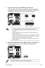
10. Power supply SMBus connector (5-pin PSUSMB1)
This connector is for the power supply SMB cable, if your power supply
supports the SMBus function.
Summary of Contents for Z8NR-D12 - Motherboard - SSI EEB 3.61
Page 1: ...Motherboard Z8NR D12 ...
Page 23: ...ASUS Z8NR D12 2 3 2 2 3 Motherboard layouts ...
Page 52: ...2 32 Chapter 2 Hardware information ...
Page 148: ...6 20 Chapter 6 Driver installation ...
Page 150: ...Appendix summary A ASUS Z8NR D12 A 1 Z8NR D12 model block diagram A 1 ...
Page 151: ...ASUS Z8NR D12 A 1 A 1 Z8NR D12 model block diagram ...


