background image

7

Quick installation guide

Quick installation guide

English

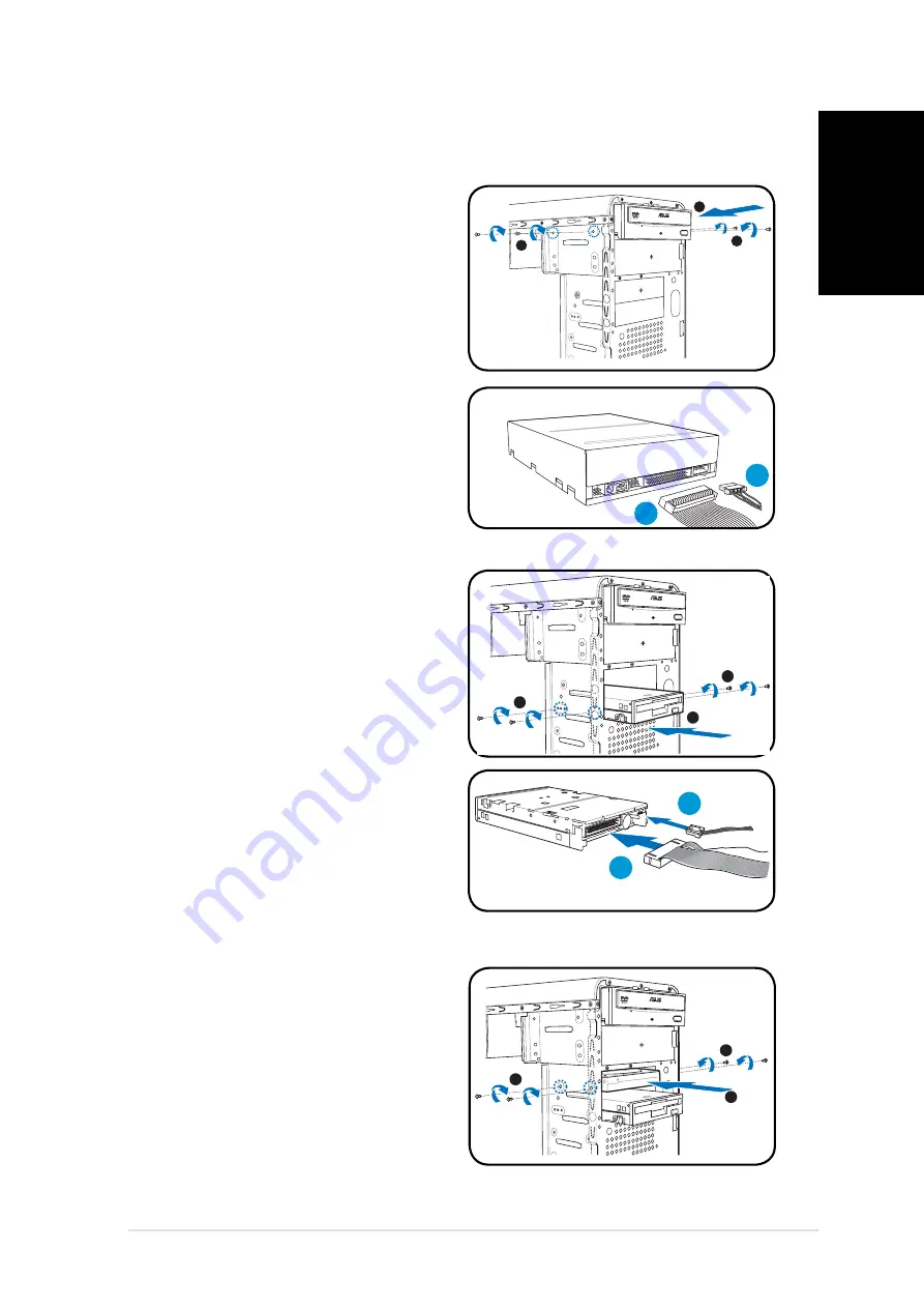
Installing storage drives

Optical drive

Optical drive

1.  Place the chassis upright, then 

remove the upper 5.25” drive 

bay metal plate cover.

2.  Insert the optical drive to the 

bay, then carefully push the 

drive until its screw holes align 

with the holes on the bay.

3.  Secure the optical drive with two 

screws on both sides of the bay.

4.  Connect the IDE (A) and power 

(B) plugs to connectors at the 

back of the drive.

3

3

2

Floppy disk drive

Floppy disk drive

1.  Place the chassis upright, then 

remove the lower 3.5” drive bay 

metal plate cover.

2. Insert 

the 

fl

 oppy disk drive to 

the bay, then carefully push the 

drive until its screw holes align 

with the holes on the bay.

3. Secure 

the 

fl

 oppy disk drive with 

two screws on both sides of the 

bay.

4.  Connect the signal (A) and 

power (B) plugs to connectors at 

the back of the drive.

3

3

2

A

B

Hard disk drive

Hard disk drive

1.  Place the chassis upright, then 

remove the upper 3.5” drive bay 

metal plate cover.

2.  Insert the hard disk drive to the 

bay, then carefully push the 

drive until its screw holes align 

with the holes on the bay.

3.  Secure the hard disk drive with 

two screws on both sides of the 

bay.

3

3

2

A

B

B

Summary of Contents for Vintage V2-AH2

Page 1: ...English Vintage V2 AH2 Barebone System Quick Installation Guide ...

Page 2: ...y cover cover Headphone port Headphone port PS 2 mouse port PS 2 mouse port Cover screw Cover screw PS 2 keyboard port PS 2 keyboard port Parallel port Parallel port Line In port Line In port Voltage selector Voltage selector Metal bracket lock Metal bracket lock Power connector Power connector DVI connector DVI connector VGA port VGA port USB 2 0 ports USB 2 0 ports Line Out port Line Out port Mi...

Page 3: ...PCI Express x1 slot 12 PCI slots 13 Metal bracket lock Selecting the voltage The systemʼs power supply unit has a 115 V 230 V voltage selector switch located beside the power connector Use this switch to select the appropriate system input voltage according to the voltage supply in your area If the voltage supply in your area is 100 127 V set the switch to 115 V If the voltage supply in your area ...

Page 4: ...ly to the right until the hinge like tabs on the right side of the assembly are exposed 5 Remove the front panel assembly then set aside 4 1 1 2 2 3 4 4 4 3 3 4 Installing a CPU 1 Locate the CPU socket then lift the socket lever to a 90º 100º angle 2 Install the CPU to the socket making sure that the CPU corner with the gold triangle matches the socket corner with a small triangle 3 Push down the ...

Page 5: ...down the retention bracket lock on the retention mechanism to secure the fan and heatsink to the module retention module base 5 Connect the CPU fan cable to the connector on the motherboard CAUTION Do not forget to connect the CPU fan connector Hardware monitoring error can occur if you fail to plug this connector NOTE Your boxed CPU should come with installation instructions for the CPU fan heats...

Page 6: ...ocket until the retaining clips snap inward Unplug the power supply before adding or removing DIMMs Failure to do so may cause damage to the motherboard and or components A DDR2 DIMM is keyed with a notch so that it fits in only one direction Do not force a DIMM into a socket to avoid damaging the DIMM 1 Remove the metal bracket lock 2 Remove the metal cover opposite the slot that you intend to us...

Page 7: ...sk drive 1 Place the chassis upright then remove the lower 3 5 drive bay metal plate cover 2 Insert the floppy disk drive to the bay then carefully push the drive until its screw holes align with the holes on the bay 3 Secure the floppy disk drive with two screws on both sides of the bay 4 Connect the signal A and power B plugs to connectors at the back of the drive 3 3 2 A B Hard disk drive Hard ...

Page 8: ...cks 2 Press the locks outward to release the bay cover 3 Push the bay cover inward then set it aside 4 Follow the same instructions to remove the 3 5 drive bay cover To reinstall the front panel assembly and side cover 1 Insert the front panel assembly hinge like tabs to the holes on the right side of the chassis 2 Swing the front panel assembly to the left then insert the hooks to the chassis unt...

Page 9: ...Français Vintage V2 AH2 Système barebone Guide de démarrage rapide ...

Page 10: ...394 Bouton dʼalimentation Bouton Reset HDD LED Ports USB 2 0 Port microphone Cache pour baies 3 5 Port casque DVI 1394 Port souris PS 2 Vis du capot Port clavier PS 2 Port parallèl Port entrée ligne Line In Sélecteur de tension Verrouillage des brackets métalliques Connecteur dʼalimentation Connecteur DVI Port VGA Ports USB 2 0 Sortie ligne Line Out Port microphone Protections métalliques pour slo...

Page 11: ...I 13 Verrouillage des brackets métalliques Choisir le voltage Lʼalimentation du système est équipée dʼun sélecteur de tension 115 V 230 V situé près du connecteur dʼalimentation Utilisez cet interrupteur pour choisir la bonne tension dʼentrée en fonction des standards utilisés dans votre région Si la tension dans votre région est de 100 127 V passez lʼinterrupteur sur 115 V Si la tension dans votr...

Page 12: ...ade vers la droite jusquʼà ce que les clapets situés sur le côté droit du panneau soient visibles 5 Retirez la façade puis mettez la de côté 4 1 Gaine dʼaération 1 2 2 3 4 4 4 3 3 Onglets du châssis 4 Installer le CPU 1 Repérez le socket du CPU puis soulever le levier du socket de 90 100 2 Placez le CPU sur le socket en vous assurant que le triangle doré sur le CPU est installé sur le triangle du ...

Page 13: ...s instructions dʼinstallation du CPU de lʼensemble dissipateur ventilateur et du module de rétention Si les instructions de cette section ne correspondent pas à celles de la documentation du CPU suivre cette dernière 4 Abaissez les loquets de fixation du module de rétention afin de sécuriser lʼensemble dissipateur ventilateur à la base du module 5 Connectez le câble du ventilateur CPU au connecteu...

Page 14: ... Retirez le verrou des protections métalliques 2 Enlevez la protection métallique du slot que vous voulez utiliser 3 Insérez le connecteur de la carte dans le slot et pressez jusquʼà ce que la carte soit en place 4 Replacez le verrou des protections métalliques Débranchez la source dʼalimentation avant dʼajouter ou de retirer des modules DIMMs Ne pas le faire peut endommager la carte mère et ou le...

Page 15: ...hâssis en position verticale puis retirez le premier cache métallique pour baie 3 5 2 Insérez le lecteur de disquettes dans la baie puis poussez le délicatement jusquʼà ce que les pas de vis sʼalignent avec ceux situés sur la baie 3 Sécurisez le lecteur de disquettes grâce à deux vis sur les deux côtés de la baie 4 Connectez le câble du lecteur de disquettes A et dʼalimentation B à lʼarrière du le...

Page 16: ...ʼextérieur afin de libérer le cache 3 Repoussez le cache vers lʼintérieur puis mettez le de côté 4 Suivez les mêmes instructions afin de retirer le cache pour baie 3 5 Pour replacer la façade et le panneau latéral 1 Insérez les clapets de la façade dans les ouvertures situées sur le côté droit du châssis 2 Pivotez la façade sur la gauche puis insérez les crochets dans le châssis jusquʼà ce que la ...

Page 17: ...Deutsch Vintage V2 AH2 Barebone System Schnellinstallationsanleitung ...

Page 18: ...nschluss Paralleler Anschluss Paralleler Anschluss Line In Anschluss Line In Anschluss Spannungsschalter Spannungsschalter Metallblendenriegel Metallblendenriegel Stromanschluss Stromanschluss DVI Anschluss DVI Anschluss VGA Anschluss VGA Anschluss USB 2 0 Anschlüsse USB 2 0 Anschlüsse Line Out Anschluss Line Out Anschluss Mikrofonanschluss Mikrofonanschluss Metallklammern der Metallklammern der E...

Page 19: ...teckplatz 12 PCI Steckplätze 13 Metallblendenriegel Das Netzteil ist mit einem 115V 230V Spannungsschalter neben dem Stromanschluss ausgestattet Verwenden Sie diesen Schalter um die passende Systemeingangsspannung entsprechend Ihrem Stromversorgungssystem in Ihrer Region auszuwählen Stellen Sie den Schalter auf 115V wenn die Stromversorgung in Ihrer Region 100V bis 127V ist Stellen Sie den Schalte...

Page 20: ...ach rechts bis die scharnierähnlichen Halterungen an der rechten Seite frei liegen 5 Entfernen Sie die Frontabdeckung und stellen Sie diese beiseite Prozessoreinbau 1 Suchen Sie den Prozessorsockel und heben den Hebel im Winkel von ca 90º 100º an 2 Stecken Sie den Prozessor in den Sockel und vergewissern Sie sich dass die Prozessorecke mit dem goldenen Dreieck mit dem kleinen Dreieck am Sockels üb...

Page 21: ...leitung für Prozessor Lüfter Kühlkörper und Befestigungsmechanismus geliefert werden Wenn die Anweisungen dieses Abschnittes nicht mit denen der Prozessordokumentation übereinstimmen folgen Sie bitte der Letzteren 4 Drücken Sie die Befestigungsklammer auf den Befestigungsmecha nismus um den Prozessor den Lüfter und den Kühlkörper an der Befestigungsgrundplatte zu sichern 5 Verbinden Sie das Kabel ...

Page 22: ... die Befestigungsklammern einrasten Ziehen Sie den Netzstecker bevor Sie die DIMMs ein oder ausbauen sonst könnte das Motherboard und oder andere Komponenten zerstört werden Ein DDR2 DIMM hat eine Kerbe so dass es nur in eine Richtung passt Stecken Sie ein DIMM nicht mit übermäßiger Kraft in einen Steckplatz ein um Schäden am DIMM zu vermeiden 1 Entfernen der Metallklammerhalterung 2 Entfernen Sie...

Page 23: ...ehäuse aufrecht hin und entfernen die untere 3 5ʼʼ Laufwerkschachtabdeckung 2 Schieben Sie das Laufwerk in den Schacht und drücken leicht bis die Befestigungslöcher am Laufwerk mit den Löchern am Schacht übereinstimmen 3 Sichern Sie das Diskettenlaufwerk mit jeweils 2 Schrauben auf jeder Seite des Schachtes 4 Verbinden Sie das Signalkabel A und das Stromversorgungskabel B mit den Steckern an der R...

Page 24: ...nen dies folgendermaßen tun 1 Suchen Sie die Abdeckungsklemmen 2 Drücken Sie zum Entfernen der Abdeckung die Klemmen nach außen 3 Drücken Sie die Abdeckung heraus und legen sie beiseite 4 Folgen Sie den gleichen Anweisungen beim Entfernen der 3 5ʼʼ Schachtabdeckung Wiedereinbau der Frontabdeckung und Seitenabdeckung 1 Führen Sie die scharnierähnlichen Klemmen in die Löcher an der rechten Gehäusese...

Page 25: ...Italiano Vintage V2 AH2 Sistema Barebone Guida all installazione veloce ...

Page 26: ...erchio Porta tastiera PS 2 Porta tastiera PS 2 Porta parallela Porta parallela Porta Linea in Entrata Porta Linea in Entrata Selettore voltaggio Selettore voltaggio Blocco staffa metallica Blocco staffa metallica Connettore alimentazione Connettore alimentazione Connettore DVI Connettore DVI Porta VGA Porta VGA Porte USB 2 0 Porte USB 2 0 Porta Linea in Uscita Porta Linea in Uscita Porta microfono...

Page 27: ...ola chassis 10 Alloggiamento PCI Express x16 11 Alloggiamento PCI Express x1 12 Alloggiamenti PCI 13 Blocco staffa metallica Lʼunità di alimentazione del sistema ha un selettore di voltaggio da 115 V 230 V posto vicino al connettore di alimentazione Utilizzare questo interruttore per selezionare il voltaggio per la propria zona Se il voltaggio è di 100 127 V impostare lʼinterruttore su 115 V Se il...

Page 28: ...eriore a destra finché non appariranno le alette a cerniera presenti sul lato destro 5 Rimuovere il pannello e metterlo da parte 4 1 1 2 2 3 4 4 4 3 3 4 Condotto Condotto dellʼaria dellʼaria Fessure del telaio Fessure del telaio Installazione della CPU 1 Localizzare il socket della CPU poi sollevare la leva per un angolo di 90º 100º 2 Installare la CPU al socket assicurandosi che lʼangolo della CP...

Page 29: ...ioni per lʼinstallazione della CPU dissipatore e per il meccanismo di bloccaggio Se le istruzioni descritte in questo paragrafo non corrispondono con la documentazione della CPU seguire il successivo 4 Premere verso il basso il blocco del supporto sul meccanismo di bloccaggio per bloccare la ventola e il dissipatore alla base del modulo 5 Connettere il cavo della ventola della CPU al connettore de...

Page 30: ...el supporto di metallo 2 Rimuovere la staffa metallica di fronte allʼalloggiamento che si intende utilizzare 3 Inserire il connettore della scheda nellʼalloggiamento poi premere la scheda fermamente finché non risulti in posizione 4 Riposizionare il blocco del supporto di metallo Installazione della DIMM 1 Localizzare i socket della DIMM nella scheda madre 2 Sbloccare il socket della DIMM premendo...

Page 31: ... verticale quindi rimuovere il coperchio metallico inferiore dellʼalloggiamento del lettore da 3 5 2 Inserire il lettore del floppy nellʼalloggiamento poi spingerlo con delicatezza finché i fori delle viti non siano allineati con quelli dellʼalloggiamento 3 Bloccare il floppy con due viti su entrambi i lati dellʼalloggiamento 4 Collegare le spine del segnale A e di alimentazione B ai connettori po...

Page 32: ...rare il coperchio 3 Premere il coperchio verso lʼinterno poi metterlo da parte 4 Seguire le stesse istruzioni per rimuovere il coperchio dellʼalloggiamento del lettore da 3 5 Per reinstallare il pannello anteriore e il coperchio laterale 1 Inserire le alette a cerniera del pannello anteriore nei fori presenti sul lato destro dello chassis 2 Ruotare lʼassemblaggio del pannello anteriore a sinistra ...

Page 33: ...Español Vintage V2 AH2 Sistema barebone Guía de instalación rápida ...

Page 34: ...uerto paralelo Puerto de entrada de línea Puerto de entrada de línea Selector de voltaje Selector de voltaje Cierre del soporte Cierre del soporte metálico metálico Conector de alimentación Conector de alimentación Conector DVI Conector DVI Puerto VGA Puerto VGA Puertos USB 2 0 Puertos USB 2 0 Puerto de salida de línea Puerto de salida de línea Puerto para micrófono Puerto para micrófono Soportes ...

Page 35: ...16 11 Ranura PCI Express x1 12 Ranuras PCI 13 Cierre del soporte metálico Seleccionar el voltaje La fuente de alimentación tiene un selector de voltaje de 115 V 230 V situado junto al conector de alimentación Utilice este conmutador para seleccionar el voltaje de entrada del sistema adecuado en función de la tensión utilizada en su región Si el voltaje de su región es de 100 127 V establezca el co...

Page 36: ...ue pueda ver las lengüetas con forma de bisagra 5 Retire el ensamblaje del panel frontal y apártelo 4 1 1 2 2 3 4 4 4 3 3 4 Conducto Conducto de aire de aire Agujeros del chasis Agujeros del chasis para lengüetas para lengüetas Instalando una CPU 1 Localice el zócalo de la CPU Levante la palanca del zócalo en un ángulo de 90º 100º 2 Instale la CPU en el zócalo asegurándose de que la esquina de la ...

Page 37: ...ventilador disipador de calor y mecanismo de retención Si las instrucciones en ésta sección no coinciden con la documentación de la CPU siga los pasos descritos en esta última 4 Empuje el bloqueo del soporte de retención en el mecanismo de retención para ajustar el ventilador y disipador de calor a la base del módulo de retención 5 Conecte el cable del ventilador de la CPU al conector de la placa ...

Page 38: ...rte metálico 2 Retire la tapa metálica situada en el lado opuesto a la ranura que desea utilizar 3 Inserte el conector de la tarjeta en la ranura y a continuación presione la tarjeta firmemente hasta que encaje en su lugar 4 Reemplace el bloqueo del soporte metálico 3 4 4 2 1 Instalar un zócalo DIMM 1 Localice los zócalos DIMM en la placa base 2 Desbloquee un zócalo DIMM presionando los broches de...

Page 39: ... en posición vertical y retire la cubierta plateada del zócalo inferior de la unidad de 3 5 2 Inserte la unidad de disquete en el zócalo empujándola cuidadosamente hasta que sus agujeros para tornillos se ajusten a éstos en el zócalo 3 Ajuste la unidad de disquete con dos tornillos en cada lateral del zócalo 4 Conecte los cables de señal A y alimentación B a los conectores en la parte trasera de l...

Page 40: ...ócalo 3 Empuje la cubierta de la caja hacia adentro y apártela 4 Siga las mismas instrucciones para retirar que con la cubierta de la caja para la unidad de 3 5 Para reinstalar el ensamblaje del panel frontal y la cubierta lateral 1 Inserte las lengüetas con apariencia de bisagra del panel principal en los agujeros de la parte derecha del chasis 2 Deslice el panel frontal a la izquierda Inserte lo...

Page 41: ...Русский Vintage V2 AH2 Barebone система Краткое руководство по установке ...

Page 42: ...лельный порт Разъем линейного входа Разъем линейного входа Переключатель Переключатель напряжения напряжения Металлический Металлический кронштейн фиксатор кронштейн фиксатор Разъем питания Разъем питания DVI разъем DVI разъем Порт VGA Порт VGA Порты USB 2 0 Порты USB 2 0 Разъем линейного выхода Разъем линейного выхода Разъем микрофона Разъем микрофона Металлические планки Металлические планки для...

Page 43: ...PCI Express x1 12 Гнезда PCI 13 Металлический кронштейн фиксатор Выбор напряжения Системный блок питания оснащен переключателем напряжений 115 В 230 В который расположен рядом с разъемом питания Используйте данный переключатель для выбора входного напряжения системы соответствующего напряжению питания в Вашем регионе Если напряжение местной электросети составляет 100 127 В установите переключатель...

Page 44: ...авой стороне передней панели чтобы полностью снять переднюю панель с корпуса 4 1 1 2 2 3 4 4 4 3 3 4 Отверстие для Отверстие для вентиляции вентиляции Пазы в корпусе Пазы в корпусе Установка процессора 1 Поднимите рычаг сокета на угол 90 100 градусов 2 Установите процессор в сокет совместите угол процессора имеющий золотой треугольник с углом сокета имеющим маленький треугольник 3 Опустите рычаг с...

Page 45: ...ЧАНИЕ Вместе с процессором в коробочной комплектации есть инструкция по установке процессора радиатора и крепежного механизма Если они отличаются от инструкций в данном разделе руководствуйтесь документацией к процессору 4 Нажмите на крепежные замки для закрепления радиатора и вентилятора к основанию модуля 5 Подключите кабель вентилятора к разъему на материнской плате ВНИМАНИЕ Не забудьте подключ...

Page 46: ...ение Во время установки и снятия модулей DIMM отключите питание В противном случае можно повредить материнскую плату и или компоненты Модуль DDR2 DIMM снабжен выемкой чтобы его можно было установить только в одном направлении НЕ применяйте силу при установке модуля DIMM в гнездо чтобы предотвратить его повреждение Иначе Вы можете повредить разъем и или модуль 1 Снимите металлическую планку 2 Сними...

Page 47: ... B Дисковод Дисковод 1 Установите корпус вертикально и удалите защитную металлическую пластину закрывающую нижний 3 5 дюймовый отсек 2 Осторожно вставте дисковод внутрь пока его отверстия для винтов не совпадут с отверстиями отсека 3 Закрепите дисковод двумя винтами с двух сторон 4 Подключите кабели сигнальный A и питания B Жесткий дисл Жесткий дисл 1 Установите корпус вертикально и удалите защитн...

Page 48: ...1 Определите местонахождение защелок крышки 2 Для освобождения крышки нажмите замки наружу 3 Вытолкните крышку внутрь 4 Следуйте тем же инструкциям для удаления другой крышки Для установки передней панели и боковых стенок 1 Вставьте петли передней панели в отверстия на правой стороне корпуса 2 Закрывайте переднюю панель пока она не встанет на место 3 Вставьте выступы крышки в верние и нижние отвер...

Page 49: ...Português Vintage V2 AH2 Sistemas barebone Guia de instalação rápida ...

Page 50: ...Porta paralela Porta da entrada de linha Porta da entrada de linha Selector de voltagem Selector de voltagem Suporte metálico de Suporte metálico de bloqueio bloqueio Conector de alimentação Conector de alimentação Conector DVI Conector DVI Porta VGA Porta VGA Portas USB 2 0 Portas USB 2 0 Porta da saída de linha Porta da saída de linha Porta do microfone Porta do microfone Suportes metálicos da S...

Page 51: ... Express x16 11 Ranhura PCI Express x1 12 Ranhuras PCI 13 Suporte metálico de bloqueio Selecção da voltagem A fonte de alimentação do sistema possui um selector de voltagem de 115 V 230 V situado ao lado do conector de alimentação Utilize este comutador para seleccionar a voltagem apropriada de acordo com a potência fornecida na sua área Se a voltagem disponível na sua área for de 100 127 V defina...

Page 52: ...s patilhas do tipo dobradiça existentes no lado direito focarem expostas 5 Remova o painel frontal e coloque o de lado 4 1 1 2 2 3 4 4 4 3 3 4 Conduta Conduta de ar de ar Orifícios das patilhas Orifícios das patilhas do chassis do chassis Instalação da CPU 1 Procure o socket da CPU e levante o num ângulo de 90 100 graus 2 Instale a CPU no socket de forma a que o canto da CPU com o triângulo dourad...

Page 53: ...ação da CPU da ventoinha do dissipador de calor e do mecanismo de retenção Se as instruções desta secção não corresponderem à documentação que acompanha a CPU siga esta última 4 Exerça pressão sobre o fecho do suporte de retenção existente no mecanismo de retenção para fixar a ventoinha e o dissipador de calor ao módulo de retenção 5 Ligue o cabo da ventoinha da CPU ao respectivo conector existent...

Page 54: ...r o mesmo 1 Remova o fecho do suporte metálico 2 Remova a tampa metálica situada em frente da ranhura que pretende utilizar 3 Introduza o conector da placa na ranhura e exerça pressão sobre a placa até esta ficar devidamente introduzida na ranhura 4 Volte a colocar o fecho do suporte metálico 3 4 4 2 1 Instalação do DIMM 1 Procure os sockets DIMM na placa principal 2 Desbloqueie um socket DIMM pre...

Page 55: ...pa metálica do compartimento superior da unidade de 3 5 2 Introduza a unidade de disquetes no compartimento e com cuidado empurre a até os respectivos orifícios dos parafusos ficarem alinhados com os orifícios existentes no compartimento 3 Fixe a unidade de disquetes com dois parafusos de ambos os lados do compartimento 4 Ligue as fichas de áudio sinal A e de alimentação B aos conectores existente...

Page 56: ... da tampa lateral nos orifícios existentes na parte superior e inferior do chassis 4 Empurre a tampa lateral na direcção do painel frontal até esta ficar devidamente encaixada 5 Fixe a tampa com os dois parafusos removidos anteriormente Remoção das tampas dos compartimentos e reinstalação do painel frontal e da tampa lateral Se instalou uma unidade óptica e ou uma unidade de disquetes remova a s t...

Page 57: ...Česky Vintage V2 AH2 Systém Barebone Stručný průvodce instalací ...

Page 58: ...S 2 Port klávesnice PS 2 Paralelní port Paralelní port Zdířka linkového vstupu Zdířka linkového vstupu Přepínač napětí Přepínač napětí Zámek kovových záslepek Zámek kovových záslepek Konektor napájení Konektor napájení Konektor DVI Konektor DVI Port VGA Port VGA Porty rozhraní USB 2 0 Porty rozhraní USB 2 0 Zdířka linkového výstupu Zdířka linkového výstupu Zdířka pro připojení mikrofonu Zdířka pro...

Page 59: ...říně 10 Slot PCI Express x16 11 Slot PCI Express x1 12 Sloty PCI 13 Zámek kovových záslepek Výběr napětí Zdroj napájení počítače je vybaven přepínačem napětí 115 V 230 V který se nachází vedle konektoru napájení Tento přepínač nastavte na hodnotu která odpovídá napětí v elektrické zásuvce ve vaší oblasti Pokud je napětí ve vaší oblasti 100 127 V nastavte přepínač na hodnotu 115 V Pokud je napětí v...

Page 60: ...l vpravo tak aby se závěsy krytu uvolnili 5 Sejměte přední panel a položte stranou 4 1 1 2 2 3 4 4 4 3 3 4 Vzduchový Vzduchový kanál kanál Otvory ve skříni Otvory ve skříni Instalace procesoru 1 Vyhledejte patici procesoru a potom zvedněte páčku patice do úhlu 900 1000 2 Zorientujte procesor nad patici tak aby roh procesoru označený zlatým trojúhelníkem odpovídal rohu patice s malým trojúhelníkem ...

Page 61: ...pro instalaci procesoru chladiče a retenčního mechanizmu Pokud pokyny v této části nejsou totožné s dokumentací k procesoru postupujte podle dokumentace k procesoru 4 Stisknutím zámku retenční konzole na retenčním mechanizmu zajistěte chladič a ventilátor k základně retenčního modulu 5 Připojte kabel ventilátoru procesoru ke konektoru na základní desce UPOZORNĚNÍ Nezapomeňte připojit konektor vent...

Page 62: ...lo k jeho poškození 1 Vyjměte kovovou záslepku 2 Vyjměte kovovou záslepku která se nachází proti slotu kterých chcete použít 3 Nasaďte konektor karty do slotu a potom zasuňte kartu zcela do slotu 4 Nasaďte kovovou záslepku 3 4 4 2 1 Instalace paměťového modulu DIMM 1 Vyhledejte patice pro paměťové moduly DIMM na základní desce 2 Stisknutím zajišťovací svorky směrem ven uvolněte patici pro paměťový...

Page 63: ...notka 1 Umístěte skříň do svislé polohy a vyjměte kovovou záslepku spodní pozice 3 5 2 Vložte disketovou jednotku do pozice a zasuňte ji na místo tak aby se otvory pro šrouby na jednotce nacházely ve stejné poloze jako otvory pro šrouby ve skříni 3 Zajistěte disketovou jednotku dvěma šroubky na obou stranách 4 Připojte zástrčku signálu A a napájecí zástrčku B ke konektorům na zadní straně jednotky...

Page 64: ...ejte zámky krytů pozic 2 Posunutím zámků směrem ven uvolněte kryt pozice 3 Posuňte kryt směrem dovnitř a položte stranou 4 Podle stejných pokynů demontujte kryt pozice 3 5 Instalace předního a bočního panelu 1 Zasuňte závěsy do otvorů na pravé straně předního panelu aby se přední panel připojil ke skříni 2 Otočte přední panel vlevo a zasuňte háčky do skříně tak aby přední panel dosedl na místo 3 Z...

Page 65: ...Polski Vintage V2 AH2 System typu Barebone Instrukcja szybkiej instalacji ...

Page 66: ...Port równoległy Port równoległy Port wejścia liniowego Port wejścia liniowego Przełącznik wyboru Przełącznik wyboru napięcia napięcia Blokada metalowych Blokada metalowych zaślepek zaślepek Złącze zasilania Złącze zasilania Złącze DVI Złącze DVI Port VGA Port VGA Porty USB 2 0 Porty USB 2 0 Port wyjścia liniowego Port wyjścia liniowego Port mikrofonu Port mikrofonu Expansion slot Expansion slot me...

Page 67: ...x1 12 Gniazda PCI 13 Blokada metalowych zaślepek Wybór napięcia Zasilacz systemu posiada przełącznik wyboru napięcia 115 V 230 V znajdujący się poniżej złącza zasilania Przełącznik ten służy do wyboru właściwego napięcia wejściowego prądu zasilającego system zgodnego z napięciem prądu zasilającego w danym obszarze Jeśli napięcie prądu zasilającego w danym obszarze wynosi 100 127 V przełącznik ten ...

Page 68: ...ch z prawej strony zespołu 5 Zdejmij zespół panela przedniego a następnie odłóż go na bok 4 1 1 2 2 3 4 4 4 3 3 4 Kanał Kanał przebiegu przebiegu powietrza powietrza Otwory zaczepu obudowy Otwory zaczepu obudowy Instalacja procesora 1 Odszukaj gniazdo procesora a następnie podnieś dźwignię gniazda pod kątem 900 1000 2 Zainstaluj procesor w gnieździe upewniając się że róg procesora oznaczony złotym...

Page 69: ...ora zespołu wentylator radiator i mechanizmu podtrzymującego Jeśli instrukcje przedstawione w tej części nie zgadzają się z dokumentacją procesora należy stosować się do instrukcji dokumentacji procesora 4 Naciśnij blokadę wspornika podtrzymującego mechanizmu podtrzymującego w celu zamocowania wentylatora i radiatora do podstawy modułu podtrzymującego 5 Podłącz kabel wentylatora procesora do złącz...

Page 70: ...oże to spowodować uszkodzenie modułu DIMM 1 Zdejmij metalową zaślepkę 2 Zdejmij metalową zaślepkę usytuowaną naprzeciw gniazda które ma zostać wykorzystane 3 Wstaw złącze karty do gniazda a następnie naciśnij mocno kartę aż do jej pełnego dopasowania do gniazda 4 Załóż metalową zaślepkę 3 4 4 2 1 Instalacja modułu DIMM 1 Zlokalizuj gniazda DIMM na płycie głównej 2 Odblokuj gniazdo DIMM naciskając ...

Page 71: ...znych 1 Ustaw obudowę pionowo a następnie zdejmij metalową płytę pokrywy dolnego napędu 3 5 2 Wstaw napęd dyskietek elastycznych do wnęki a następnie ostrożnie pchnij napęd aż do wyrównania otworów na śruby w napędzie z otworami we wnęce 3 Zamocuj napęd dyskietek elastycznych dwiema śrubami po obu stronach wnęki 4 Podłącz wtyki sygnałowe A i zasilania B do złączy z tyłu napędu Napęd dysku twardego...

Page 72: ...tworów w górnej i w dolnej części obudowy 4 Naciskaj pokrywę boczną w kierunku panela przedniego aż do jej dopasowania na miejsce 5 Zamocuj pokrywę dwiema wcześniej odkręconymi śrubami Zdejmowanie pokryw wnęk i zakładanie zespołu panela przedniego i pokrywy bocznej Po zainstalowaniu napędu dysku optycznego i lub napędu dyskietek elastycznych przed zamontowaniem ich w obudowie należy zdjąć pokrywę ...

Page 73: ...Magyar Vintage V2 AH2 Barebone rendszer Gyors üzembe helyezési útmutató ...

Page 74: ...csavarja PS 2 billentyűzet port PS 2 billentyűzet port Párhuzamos port Párhuzamos port Vonalbemeneti port Vonalbemeneti port Feszültségváltó Feszültségváltó Bővítőkártya rögzítő Bővítőkártya rögzítő retesz retesz Tápcsatlakozó Tápcsatlakozó DVI csatlakozó DVI csatlakozó VGA port VGA port USB 2 0 portok USB 2 0 portok Vonalkimeneti port Vonalkimeneti port Mikrofon port Mikrofon port Bővítőkártya ny...

Page 75: ... 11 PCI Express x1 foglalat 12 PCI foglalatok 13 Bővítőkártya rögzítő retesz A feszültség kiválasztása A rendszer tápegysége 115 V 230 V feszültségválasztó kapcsolóval rendelkezik amely a tápcsatlakozó mellett található Ez a kapcsoló a területének megfelelő tápfeszültség kiválasztására szolgál Amennyiben az Ön területén 100 127 V a hálózati feszültség állítsa a kapcsolót 115 V ra Amennyiben az Ön ...

Page 76: ...zerű nyelvek a szerelvény a jobb oldalán 5 Távolítsa el az előlapot majd tegye félre 4 1 1 2 2 3 4 4 4 3 3 4 Szellőzővezeték Szellőzővezeték Rések az oldallapon Rések az oldallapon lévő fülekhez lévő fülekhez A CPU beszerelése 1 Keresse meg a CPU foglalatot majd emelje fel a foglalat rögzítő karját úgy hogy 90 100 fokos szögben álljon 2 Illessze a CPU t a foglalatba úgy hogy az CPU n lévő aranyszí...

Page 77: ...nia kell a CPU a ventilátor hűtőborda szerelvény és rögzítőszerkezet beszerelési utasítását Amennyiben eltérés lenne a jelen fejezet utasításai és a CPU dokumentációja között az utóbbi a mérvadó 4 Nyomja le tartókeret zárját a rögzítő szerelvényre hogy a ventilátort és a hűtőbordát a tartómodulhoz rögzítse 5 Csatlakoztassa a CPU ventilátor tápkábelét az alaplap CPU ventilátor csatlakozójához FIGYE...

Page 78: ... modult 1 Távolítsa el a fémkeret reteszét 2 Távolítsa el ahhoz a foglalathoz tartozó fém fedőlemezt amelyet használni szándékozik 3 Helyezze be a kártya csatlakozóját a foglalatba majd határozott mozdulattal nyomja le a kártyát amíg a helyére nem illeszkedik 4 Szerelje vissza a fémkeret reteszét 3 4 4 2 1 DIMM beszerelése 1 Keresse meg a DIMM foglalatokat az alaplapon 2 Oldja a DIMM foglalat rögz...

Page 79: ...ázat a megfelelő irányba majd szerelje le az alsó 3 5 hüvelykes meghajtó bővítőhely fémlemezét 2 Helyezze a hajlékonylemez meghajtót a bővítőhelyre majd óvatosan tolja be amíg a rögzítésére szolgáló lyukak és a bővítőhely lyukai egy vonalba nem esnek 3 Rögzítse a hajlékonylemez meghajtót két két csavarral mindkét oldalon 4 Csatlakoztassa a jel A és tápkábel B dugóit a meghajtó hátulján lévő csatla...

Page 80: ...Illessze az oldalsó fedél kampóit a ház felső és alsó nyílásaiba 4 Tolja az oldalsó fedelet az elülső panel irányába amíg a helyére nem illeszkedik 5 Rögzítse a fedelet a két korábban eltávolított csavarral A meghajtórekeszek fedeleinek eltávolítása az előlap és az oldallemez visszaszerelése Ha beszerelte az optikai illetve hajlékonylemezes meghajtókat távolítsa el az előlapból a megfelelő bőv ítő...

Reviews: