background image

^

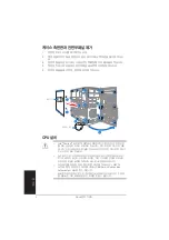
΂ΦΚΔΜ͑昪獞͑儆決姢

䚐ạ㛨

FSX#㠒ᇦ#㲅⟛㕖#☎㍂#

p•›Œ“

´

GwŒ•›œ”

´

G[Vp•›Œ“

´

GwŒ•›œ”

´

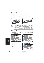
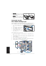
GkGsnh^^\G䘸⦐㉬㉐⏈G㺐㤵㢌Gⵐ㜨G㦤ᶤḰG㉥

⏙㡸G㠸䚨G䏭ⷸGḔ㙼═G䣏㐥䆠㝴G䑠㡸G㇠㟝䚨㚰G䚝⏼␘UG

ˍ

G

p•›Œ“

´

GwŒ•›œ”

´

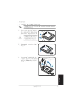
G[G䘸⦐㉬㉐⪰GẠ㢹䚐Gᷱ㟤SGẠ㉥䖼G㩅㜄Gjw|G䑜ḰG䣏㐥䆠

ᴴG䔠䚜╌㛨G㢼㏩⏼␘UG⬀㚱Gjw|⪰G♤⦐GẠ㢹䚌㊜␘⮨SGp•›Œ“

´

G㢬㫑G⭴䐤G

ⵝ䛙G䣏㐥䆠㝴G䑠㡸G㇠㟝䚨G㨰㐡㐐㝘UG

ˍ

G

p•›Œ“

´

GwŒ•›œ”

´

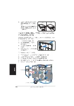
G[Gsnh^^\G䣏㐥䆠㝴G䑠㡴G㉘㾌㐐G⓸ẠᴴG䙸㟈㛺⏈G䙴Gⵝ㐑

㢹⏼␘UG

⬀㚱Gjw|G䣏㐥䆠㝴G䑠㡸G♤⦐GẠ㢹䚌㊜␘⮨SG䣏㐥䆠㝴G䑠㡸G㉘㾌䚌ὤG㤸㜄G㒜
⭴GἬ⫠㏘⪰Gjw|G䣏㐥䆠㝴Gjw|㜄GḜḔ⨜Gⵐ⢰G㨰㐡㐐㝘UGG

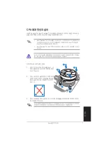
jw|G䣏㐥䆠㝴G䑠G㉘㾌Gⵝⷉ

XUG

㉘㾌═Gjw|G㠸㜄G䣏㐥䆠⪰G⋇ḔSGḔ
㥉䙴㡸G⫼⒈⸨☐㢌GẠ⮁G㠸㾌㜄G㢰㾌
㐐䁐G㨰㐡㐐㝘UG

ZUG

䣑㐥䆠㝴G䑠㡸G⯜▄G㉘㾌䚐G䟸SGjw|G䑠G䀴㢨⽈㡸G⫼⒈⸨☐㜄G㠸㾌䚐G䀘≙䉤
㜄G㜤ᷤ䚨G㨰㐡㐐㝘UG

h

i

i

YUG

䣏㐥䆠㢌G㋄ㇵ㡸Gⵝ㫴䚌ὤG㠸䚨G␴ᴵ
㉔㜄G㠸㾌䚐GYᵐ㢌GḔ㥉䙴㡸G┍㐐㜄G
ⴴ㛨G≗㛨G㨰㐔䟸SG䑠㡸G㠸㾌㐐䁐G㨰
㐡㐐㝘UG

jw|G䑠G䀴㢨⽈㡸G䀘≙䉤㜄Gⵌ☐㐐G㜤ᷤ䚨G㨰㐡㐐㝘HG⬀㚱G䀴㢨⽈㢨G䀘≙䉤㜄G
㜤ᷤ╌㛨G㢼㫴G㙾㡰⮨SG䚌☐㠜㛨Gᵄ㐐G㣙㾌㜄㉐G㜄⤠ᴴGⵐ㈑䚝⏼␘UGG

h

h

i

i

X

X

h

Summary of Contents for V2-PH1

Page 1: ...English Vintage2 PH1 Barebone System Quick Installation Guide ...

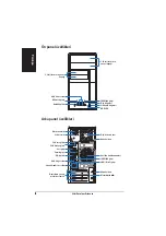
Page 2: ...rew Cover screw Cover screw Cover screw PS 2 keyboard port PS 2 keyboard port PS 2 keyboard port PS 2 keyboard port PS 2 keyboard port Parallel port Parallel port Parallel port Parallel port Parallel port Voltage selector Voltage selector Voltage selector Voltage selector Voltage selector Metal bracket lock Metal bracket lock Metal bracket lock Metal bracket lock Metal bracket lock Power connector...

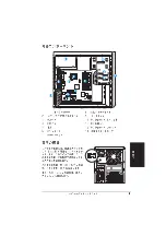
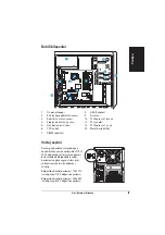
Page 3: ...SIS USB78 USB56 CLRTC PCI1 Intel GMCH 945G Intel ICH7 DDR DIMM_A2 64 bit 240 pin module DDR DIMM_B1 64 bit 240 pin module DDR DIMM_B2 64 bit 240 pin module CHA_FAN CPU_FAN PRI_IDE EATXPWR PCI2 SPDIF_OUT Intel 82573L PS 2KBMS T Mouse B Keyboard PCIEX1_1 PCIEX16 COM1 PARALLEL PORT VGA PLED SATA1 SATA2 SATA4 SATA3 BUZZ PWR_FAN SPEAKER COM2 ALC882 TI TSB43AB22A IE1394_2 LGA775 LAN_USB34 AUDIO USB1 USB...

Page 4: ...boxed Intel Pentium 4 LGA775 processor package should come with installation instructions for the CPU heatsink and the retention mechanism If the instructions in this section do not match the CPU documentation follow the latter Check your motherboard to make sure that the PnP cap is on the CPU socket and the socket contacts are not bent Contact your retailer immediately if the PnP cap is missing o...

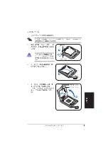
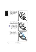
Page 5: ...nstalling a CPU A A A A A B B B B B 3 3 3 3 3 2 Press the load lever with your thumb A then move it to the left B until it is released from the retention tab 3 Lift the load lever in the direction of the arrow to a 135º angle Load lever Load lever Load lever Load lever Load lever Retention tab Retention tab Retention tab Retention tab Retention tab 4 Lift the load plate with your thumb and forefin...

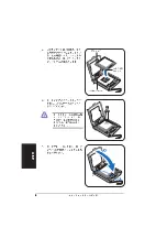
Page 6: ...the load lever B until it snaps into the retention tab 5 Position the CPU over the socket making sure that the gold triangle is on the bottom left corner of the socket then fit the socket alignment key into the CPU notch A A A A A B B B B B 6 Apply Thermal Interface Material on the CPU before reinstalling the heatsink and fan assembly DO NOT DO NOT DO NOT DO NOT DO NOT eat the Thermal Interface Ma...

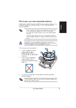
Page 7: ...mes in a push pin design and requires no tool to install If you purchased a separate CPU heatsink and fan assembly make sure that a Thermal Interface Material is properly applied to the CPU heatsink or CPU before you install the heatsink and fan assembly To install the CPU heatsink and fan 1 Place the heatsink on top of the installed CPU making sure that the four fasteners match the holes on the m...

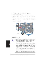
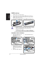
Page 8: ...et 4 Push the DIMM to the socket until the retaining clips snap inward Unplug the power supply before adding or removing DIMMs Failure to do so may cause damage to the motherboard and or components A DDR DIMM is keyed with a notch so that it fits in only one direction Do not force a DIMM into a socket to avoid damaging the DIMM 2 Remove the metal bracket lock 1 Remove the metal cover opposite the ...

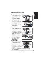
Page 9: ...rive Floppy disk drive Floppy disk drive Floppy disk drive 1 Place the chassis upright then remove the lower 3 5 drive bay metal plate cover 2 Insert the floppy disk drive to the bay then carefully push the drive until its screw holes align with the holes on the bay 3 Secure the floppy disk drive with two screws on both sides of the bay 4 Connect the signal A and power B plugs to connectors at the...

Page 10: ...hassis To do this 1 Locate the bay cover locks 2 Press the locks outward to release the bay cover 3 Push the bay cover inward then set it aside 4 Follow the same instructions to remove the 3 5 drive bay cover Air duct Air duct Air duct Air duct Air duct To reinstall the front panel assembly and side cover 1 Insert the front panel assembly hinge like tabs to the holes on the right side of the chass...

Page 11: ...Français Vintage2 PH1 Système barebone Guide de démarrage rapide ...

Page 12: ...llèl Sélecteur de tension Sélecteur de tension Sélecteur de tension Sélecteur de tension Sélecteur de tension Verrouillage des Verrouillage des Verrouillage des Verrouillage des Verrouillage des brackets métalliques brackets métalliques brackets métalliques brackets métalliques brackets métalliques Connecteur Connecteur Connecteur Connecteur Connecteur d alimentation d alimentation d alimentation ...

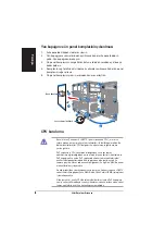
Page 13: ... votre région Si la tension dans votre région est de 100 127 V passez l interrupteur sur 115 V Si la tension dans votre région est de 200 240 V passez l interrupteur sur 230 V CR2032 3V Lithium Cell CMOS Power CD Super I O Intel FWH 4Mb ATX12V FLOPPY AAFP DDR DIMM_A1 64 bit 240 pin module SB_PWR F_PANEL CHASSIS USB78 USB56 CLRTC PCI1 Intel GMCH 945G Intel ICH7 DDR DIMM_A2 64 bit 240 pin module DDR...

Page 14: ...glets du châssis Installer le CPU Dans la boîte de votre processeur Intel Pentium 4 LGA775 vous devriez trouver les instructions d installation pour le CPU le dissipateur et le méchanisme de rétention Si les instructions de cette section ne correspondent pas à la documentation du CPU suivez cette dernière A l achat de la carte mère assurez vous que le cache PnP est présent sur le socket et que les...

Page 15: ... de Loquet de rétention rétention rétention rétention rétention P P P P Pl a q u e l a q u e l a q u e l a q u e l a q u e Plaque de Plaque de Plaque de Plaque de Plaque de protection protection protection protection protection A A A A A B B B B B Pour éviter d endommager les broches du socket ne retirez pas le cache PnP sauf pour installer le CPU 2 Pressez le levier avec votre pouce A et glissez ...

Page 16: ...coche du CPU encoche du CPU encoche du CPU 7 Refermez la plaque A puis poussez le levier B jusqu à ce qu il soit accroché par le loquet de rétention 5 Placez le CPU au dessus du socket en vous assurant que le triangle doré soit dans le coin inférieur gauche du socket La clef d alignement du socket doit correspondre avec l encoche du CPU 6 Appliquez de la pâte thermique sur le CPU avant d installer...

Page 17: ...ssite aucun outil pour l installer Si vous achetez un ensemble dissipateur ventilateur à part assurez vous d avoir correctement appliqué le matériau d interface thermique sur le CPU ou sur le dissipateur avant d installer l ensemble Pour installer l ensemble dissipateur ventilateur 1 Placez le dissipateur sur le processeur en vous assurant que les quatres systèmes de serrage correspondent aux trou...

Page 18: ...ue les clips de rétention se referment 2 Retirez le verrou des protections métalliques 1 Enlevez la protection métallique du slot que vous voulez utiliser 3 Insérez le connecteur de la carte dans le slot et pressez jusqu à ce que la carte soit en place 4 Replacez le verrou des protections métalliques 1 1 1 1 1 2 2 2 2 2 3 3 3 3 3 4 4 4 4 4 Débranchez la source d alimentation avant d ajouter ou de ...

Page 19: ... Installer un lecteur de disquettes Installer un lecteur de disquettes Installer un lecteur de disquettes 1 Mettez le châssis en position verticale puis retirez le premier cache métallique pour baie 3 5 2 Insérez le lecteur de disquettes dans la baie puis poussez le délicatement jusqu à ce que les pas de vis s alignent avec ceux situés sur la baie 3 Sécurisez le lecteur de disquettes grâce à deux ...

Page 20: ... côté 4 Suivez les mêmes instructions afin de retirer le cache pour baie 3 5 Pour replacer la façade et le panneau latéral 1 Insérez les clapets de la façade dans les ouvertures situées sur le côté droit du châssis 2 Pivotez la façade sur la gauche puis insérez les crochets dans le châssis jusqu à ce que la façade tienne bien en place 3 Insérez les crochets du panneau latéral dans les ouvertures s...

Page 21: ...Vintage2 PH1 ...

Page 22: ...2 2 2 2 2 REAR S P K LINE IN FRONT MIC IN SIDE S P K C T R BASS 5 25 Reset USB 2 0 PS 2 PS 2 VGA USB 2 0 LAN RJ 45 1394 1394 ...

Page 23: ... bit 240 pin module DDR DIMM_B2 64 bit 240 pin module CHA_FAN CPU_FAN PRI_IDE EATXPWR PCI2 SPDIF_OUT Intel 82573L PS 2KBMS T Mouse B Keyboard PCIEX1_1 PCIEX16 COM1 PARALLEL PORT VGA PLED SATA1 SATA2 SATA4 SATA3 BUZZ PWR_FAN SPEAKER COM2 ALC882 TI TSB43AB22A IE1394_2 LGA775 LAN_USB34 AUDIO USB1 USB2 Bottom 1394 Top 1 2 5 25 3 4 5 6 CPU 7 8 9 10 PCI Express x16 11 PCI 12 PCI Express x1 13 100 127V 1...

Page 24: ...4 4 4 4 4 1 2 3 4 5 1 Air duct 1 2 2 3 4 CPU LGA775 LGA775 Return Merchandise Authorization RMA CPU CPU CPU ...

Page 25: ...5 5 5 5 5 1 2 CPU 4 CPU 3 A B A B ...

Page 26: ...6 6 6 6 6 5 CPU CPU CPU 7 6 CPU A B ...

Page 27: ...7 7 7 7 7 CPU Intel Pentium 4 Pentium D LGA775 A A B B CPU_FAN1 CPU Hardware monitoring errors 3 CPU_FAN1 1 CPU 2 Intel Pentium 4 LGA775 CPU Intel 4 pin Intel Pentium 4 LGA775 A B B A 1 1 CPU ...

Page 28: ...8 8 8 8 8 1 2 3 4 2 1 3 4 1 2 3 4 DDR DIMM ...

Page 29: ...9 9 9 9 9 1 2 5 25 3 4 A IDE B C 3 3 2 1 2 3 4 A B 3 3 2 A B A C B 1 2 3 3 3 2 ...

Page 30: ...1 0 1 0 1 0 1 0 1 0 4 SATA Serial ATA IDE IDE SATA IDE 1 2 3 4 3 5 5 Air duct 5 4 3 2 1 1 2 3 4 5 2 3 ...

Page 31: ...Vintage2 PH1 ...

Page 32: ...2 2 2 2 2 REAR S P K LINE IN FRONT MIC IN SIDE S P K C T R BASS 5 25 Reset USB 2 0 PS 2 PS 2 VGA USB 2 0 LAN RJ 45 1394 1394 ...

Page 33: ... bit 240 pin module DDR DIMM_B2 64 bit 240 pin module CHA_FAN CPU_FAN PRI_IDE EATXPWR PCI2 SPDIF_OUT Intel 82573L PS 2KBMS T Mouse B Keyboard PCIEX1_1 PCIEX16 COM1 PARALLEL PORT VGA PLED SATA1 SATA2 SATA4 SATA3 BUZZ PWR_FAN SPEAKER COM2 ALC882 TI TSB43AB22A IE1394_2 LGA775 LAN_USB34 AUDIO USB1 USB2 Bottom 1394 Top 1 2 5 25 3 4 5 6 CPU 7 8 9 10 PCI Express x16 11 PCI 12 PCI Express x1 13 100 127V 1...

Page 34: ...4 4 4 4 4 1 2 3 4 5 1 Air duct 1 2 2 3 4 CPU LGA775 LGA775 Return Merchandise Authorization RMA CPU CPU CPU ...

Page 35: ...5 5 5 5 5 1 2 CPU 4 CPU 3 A B A B ...

Page 36: ...6 6 6 6 6 5 CPU CPU CPU 7 6 CPU A B ...

Page 37: ...7 7 7 7 7 CPU Intel Pentium 4 Pentium D LGA775 A A B B CPU_FAN1 CPU Hardware monitoring errors 3 CPU_FAN1 1 CPU 2 Intel Pentium 4 LGA775 CPU Intel 4 pin Intel Pentium 4 LGA775 A B B A 1 1 CPU ...

Page 38: ...8 8 8 8 8 1 2 3 4 2 1 3 4 1 2 3 4 DDR DIMM ...

Page 39: ...9 9 9 9 9 1 2 5 25 3 4 A IDE B C 3 3 2 1 2 3 4 A B 3 3 2 A B A C B 1 2 3 3 3 2 ...

Page 40: ...1 0 1 0 1 0 1 0 1 0 4 SATA Serial ATA IDE IDE SATA IDE 1 2 3 4 3 5 5 Air duct 5 4 3 2 1 1 2 3 4 5 2 3 ...

Page 41: ...Vintage2 PH1 ...

Page 42: ...2 2 2 2 2 REAR S P K LINE IN FRONT MIC IN SIDE S P K C T R BASS ...

Page 43: ...dule DDR DIMM_B2 64 bit 240 pin module CHA_FAN CPU_FAN PRI_IDE EATXPWR PCI2 SPDIF_OUT Intel 82573L PS 2KBMS T Mouse B Keyboard PCIEX1_1 PCIEX16 COM1 PARALLEL PORT VGA PLED SATA1 SATA2 SATA4 SATA3 BUZZ PWR_FAN SPEAKER COM2 ALC882 TI TSB43AB22A IE1394_2 LGA775 LAN_USB34 AUDIO USB1 USB2 Bottom 1394 Top 6 6 6 6 6 1 1 1 1 1 2 2 2 2 2 3 3 3 3 3 4 4 4 4 4 1 1 1 1 13 3 3 3 3 1 1 1 1 11 1 1 1 1 9 9 9 9 9 7...

Page 44: ...4 4 4 4 4 ...

Page 45: ...5 5 5 5 5 A A A A A B B B B B 3 3 3 3 3 O O A A A A A B B B B B ...

Page 46: ...6 6 6 6 6 A A A A A B B B B B ...

Page 47: ...7 7 7 7 7 A A A A A A A A A A B B B B B B B B B B 1 1 1 1 1 1 1 1 1 1 A B B A ...

Page 48: ...8 8 8 8 8 1 1 1 1 1 2 2 2 2 2 3 3 3 3 3 4 4 4 4 4 ...

Page 49: ...9 9 9 9 9 3 3 2 3 3 2 3 3 2 C C C C C B B B B B A A A A A B B B B B A A A A A ...

Page 50: ...1 0 1 0 1 0 1 0 1 0 2 2 2 2 2 1 1 1 1 1 3 3 3 3 3 2 2 2 2 2 5 5 5 5 5 5 5 5 5 5 1 1 1 1 1 1 1 1 1 1 2 2 2 2 2 2 2 2 2 2 4 4 4 4 4 ...

Page 51: ...䚐ạ㛨 䚐ạ㛨 䚐ạ㛨 Vintage2 PH1 㙆 㙆 ΦΚΔΜ 昪獞 儆決姢 ΦΚΔΜ 昪獞 儆決姢 ...

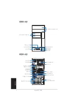
Page 52: ... P K C T R BASS UY 㢬㾌G 㢨 Gⷔ㢨G䀘ⶸ plllGXZ G䔠䏬 㤸㠄Gⶸ䏰 Gⶸ䏰 okkGslk ziGYUWG䔠䏬 㢨䆠 䔠G䔠䏬G ZU 㢬㾌G 㢨 Gⷔ㢨G䀘ⶸ 䜘 䔤G䔠䏬 wzVYG 㟤 G䔠䏬 䀘ⶸG wzVYG䇘 G䔠䏬 䑜 G䔠䏬 㤸㚉G 䉤 Ἴ G 䇫G㣔ἼG㣙㾌 㤸㠄G䀘 䉤 㐐 㛰G䔠䏬 G nhG䔠䏬 ziGYUWG䔠䏬 _G㵸 G㝘 㝘G䔠䏬 䞉㣙G GVGἼ G 䇫G 䑀㠀G 䙀 㢨G䑠 䀴㢨 G䑠GⵤὤẠ shuGOyqT PG䔠䏬 䀘ⶸG plllGXZ G䔠䏬 ...

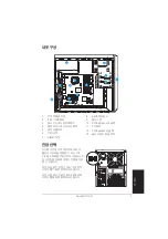
Page 53: ...45G Intel ICH7 DDR DIMM_A2 64 bit 240 pin module DDR DIMM_B1 64 bit 240 pin module DDR DIMM_B2 64 bit 240 pin module CHA_FAN CPU_FAN PRI_IDE EATXPWR PCI2 SPDIF_OUT Intel 82573L PS 2KBMS T Mouse B Keyboard PCIEX1_1 PCIEX16 COM1 PARALLEL PORT VGA PLED SATA1 SATA2 SATA4 SATA3 BUZZ PWR_FAN SPEAKER COM2 ALC882 TI TSB43AB22A IE1394_2 LGA775 LAN_USB34 AUDIO USB1 USB2 Bottom 1394 Top ᖞ ቖ XUG 㤸 G䑜 G䀘ⶸ YUG ...

Page 54: ...Y Z Z Z Z ˍG p Gw G Gsnh G䘸 G䑜䇘㫴㜄 Gjw SG䣏㐥䆠SG 䊄 G G 㾌G ᴴGⵌ 㐐G䔠䚜 㛨G㢼 UG 㚱G G 㾌Gᴴ㢨 㢌G 㟝 ḰGjw GẠ㢹㐐G㥐ḩ Gjw G 㾌Gⱬ 㢌G 㟝㢨G SGjw G 㾌Gⱬ 㢌G 㫴㐐G 䚡㡸G G㨰㐡㐐㝘UG ˍG w wG㿕㢨Gjw G 䁇㜄G㢼 㫴GẠ 㥬G㢼㫴 G㙾㡴㫴G䞉㢬䚨G㨰㐡㐐㝘UG 㚱Gw wG㿕㢨G㛺ᶤ G ㇵ 㛨G㢼 SG㪽㐐GẠ㢹㷌㜄Gⱬ㢌䚨G㨰㐡㐐㝘UG 㟨 G㩅㜄G䑀 G㥐䖼㜄G 䚨 Ghz zᴴG 㟝㡸G㵹㢸㬅 UGG ˍG G 㾌䚐G䟸㜄G㿕㡴G G Ḵ䚨G㨰㐡㐐㝘UGsnh G 䁇㜄G㿕㢨G㢼㡸Gᷱ㟤㜄 Ghz z㜄 GythOy Gt G h PG㟈㷡㡸G䚔G G㢼 UGG ˍG 㝠ⵈ 㫴G㙾㡴Gⵝⷉ㡰 Gjw G 㾌V㥐ᶤ䚌㜠G㥐䖼㢨G ㇵ Gᷱ㟤SGw wG㿕 㡸G㢷㛨ⶸ...

Page 55: ...GḔ㥉G ⶸᴴG㞰㯱㜄G㠸 㾌䚌 G䚨㨰㐡㐐㝘UGG jw G 㾌䚌㫴G㙾㡴Gᷱ㟤SG 䁇G䙴㜄G ㇵ㡸Gⵝ㫴䚌ὤG㠸䚨G w wG㿕㡸G㥐ᶤ䚌㫴G 㐡㐐㝘UGGG h i Z YUG 㛸㫴G ᴴ OhP㡸G㢨㟝䚨G ⶸ G G䟸S ⶸᴴG 䊓 G䈡㜄 G ᾀ㫴G㞰㯱㡰 Gⴴ㛨G㨰㐡㐐㝘UOiP ZUG ⶸ G䞈 䖐Gⵝ䛙㡰 GXZ ÀG㝠 G 㨰㐡㐐㝘UG Ḕ㥉G ⶸ 䊄 G䈡 UG 㛸㫴㝴Gᶴ㫴 G㢨㟝䚨G ⶸ GXWWÀG ᴴ G 㛨G㝠 G䟸OhPSGḔ㥉G䙀 㢨䏬 㜄 Gw wG㿕㡸Gⴴ㛨G㥐ᶤ䚨G㨰㐡㐐 㝘UOiP Ḕ㥉G䙀 㢨䏬 w wG㿕 h i ...

Page 56: ... ḔOhPSG 䊄 㜄G ᶬ ᾀ㫴G ⶸ Gⴴ㛨G 㙸G㨰㐡 㐐㝘OiPU UG 䁇㢌G㧀㽕G䚌 㜄G䖐㐐 GἼㇽG ㇰᴵG 䆠 G䞉㢬䚌G䟸SG 䁇G㠸㜄G jw G 㙸G㨰㐡㐐㝘UG 䁇㢌G㥉 䇘 Gjw G䝼㜄G G G 㛨G 㢼 UG h i UG jw 㜄G䣏G㐥䆠㝴G䑠㡸G 㾌䚌ὤG㤸 㜄G㒜 GἬ Gⵐ G㨰㐡㐐㝘UG 㒜 GἬ G㤼 G 㫴G 㐡㐐 㫴G 㐡㐐 㝘 㝘UG 㚱G 㢨 G䙰 㜄G 㚌 SG㪽㐐G㙯㛨 ḔG 㠄㜄 G㫸 㵤㡸Gⵏ㙸G㨰㐡㐐㝘UG jw G䝼 ...

Page 57: ...snh G䣏㐥䆠㝴G䑠㡴G 㾌㐐G ẠᴴG䙸㟈㛺 G䙴Gⵝ㐑 㢹 UG 㚱Gjw G䣏㐥䆠㝴G䑠㡸G GẠ㢹䚌 SG䣏㐥䆠㝴G䑠㡸G 㾌䚌ὤG㤸㜄G㒜 GἬ Gjw G䣏㐥䆠㝴Gjw 㜄GḜḔ Gⵐ G㨰㐡㐐㝘UGG jw G䣏㐥䆠㝴G䑠G 㾌Gⵝⷉ XUG 㾌 Gjw G㠸㜄G䣏㐥䆠 G ḔSGḔ 㥉䙴㡸G 㢌GẠ G㠸㾌㜄G㢰㾌 㐐䁐G㨰㐡㐐㝘UG ZUG 䣑㐥䆠㝴G䑠㡸G G 㾌䚐G䟸SGjw G䑠G䀴㢨 㡸G 㜄G㠸㾌䚐G䀘 䉤 㜄G㜤 䚨G㨰㐡㐐㝘UG h i i YUG 䣏㐥䆠㢌G ㇵ㡸Gⵝ㫴䚌ὤG㠸䚨G ᴵ 㜄G㠸㾌䚐GYᵐ㢌GḔ㥉䙴㡸G 㐐㜄G ⴴ㛨G 㛨G㨰㐔䟸SG䑠㡸G㠸㾌㐐䁐G㨰 㐡㐐㝘UG jw G䑠G䀴㢨 㡸G䀘 䉤㜄Gⵌ 㐐G㜤 䚨G㨰㐡㐐㝘HG 㚱G䀴㢨 㢨G䀘 䉤㜄G 㜤 㛨G㢼㫴G㙾㡰 SG䚌 㠜㛨Gᵄ㐐G㣙㾌㜄 G㜄 ᴴGⵐ 䚝 UGG h h i i ...

Page 58: ...㐡㐐 㝘UG UG Ḕ㥉G䆨 㢨Gkptt㡸GḔ㥉䚔G ᾀ㫴Gkptt㡸G G㨰㐡㐐㝘UGG ˍG ⵌ 㐐G䑀㠀G 䙀 㢨 Gⅸ㐔G䟸SGkptt㡸G 㾌䚌ᶤ G㥐ᶤ䚨G㨰㐡㐐㝘UG G 䖼㜄G ㇵ㡸G㚰ὤ䚔G G㢼 UG ˍG kkyGkptt㡴G㩅ᴸ㜄G䝼㢨G㢼㛨G䚐G㯱Gⵝ䛙㡰 G㣙㵝䚔G G㢼 UG kptt㡸G 䁇㜄G 㡸G G ⱨGᵉ䚐G䣌㡸G㨰 Gkptt㜄G ㇵ㡸G㚰ὤ䚔G G㢼 UG YUG Ἴ G 䇫G㣔ἼG㣙㾌 G㥐ᶤ䚨G 㨰㐡㐐㝘UG XUG 㟝䚔G 㢌GἼ G䀘ⶸ G㥐ᶤ 䚨G㨰㐡㐐㝘UG ZUG 㜄G㾨 G䀘 䉤 G㣙㵝䚐G䟸SG 㝸㤸䢼GḔ㥉㐐䁐G㨰㐡㐐㝘UG UG Ἴ G 䇫G㣔ἼG㣙㾌 G 㐐G 㾌䚨G㨰㐡㐐㝘UG X Y Z ...

Page 59: ...㜤 䚨G㨰㐡㐐㝘UG 3 3 2 稒嵢穂 娚枪畲 姢岂決挒 稒嵢穂 娚枪畲 姢岂決挒 XUG 䀴㢨 Gⵈ G 㟨G䟸SGZU IG 㢨 Gⷔ㢨GἼ G䙀 㢨䏬G䀘ⶸ G㥐ᶤ 䚨G㨰㐡㐐㝘UGG YUG 䙀 䙰G 䆠 G㣙㵝䚐G䟸SGⷔ㢨㢌G Ạ ḰG䀴㢨 㢌GẠ 㢨G㢰㾌䚔G ᾀ㫴G㦤㐠 Gⴴ㛨G㨰㐡㐐㝘UG ZUG Yᵐ㢌G G㢨㟝䚌㜠G䙀 䙰G 䆠 GḔ㥉㐐䁐G㨰㐡㐐㝘U UG 㐔䝬G䀴㢨 OhPSG㤸㠄G䀴㢨 OiP㡸G 㢨 G䟸 㜄G㠸㾌䚐G䀘 䉤㜄G㜤 䚨G㨰㐡㐐㝘UG 3 3 2 穞姢娚枪畲 姢岂決挒 穞姢娚枪畲 姢岂決挒 XUG 䀴㢨 Gⵈ G 㟨G䟸SGZU IG 㢨 Gⷔ㢨GἼ G䙀 㢨䏬G䀘ⶸ G㥐ᶤ 䚨G㨰㐡㐐㝘UGG YUG 䚌 䆠 G㣙㵝䚐G䟸SGⷔ㢨㢌GẠ ḰG䀴㢨 㢌GẠ 㢨G㢰㾌䚔G ᾀ 㫴G㦤㐠 Gⴴ㛨G㨰㐡㐐㝘U ZUG Yᵐ㢌G G㢨㟝䚌㜠G䚌 䆠 G...

Page 60: ...㤸㜄G 㢀㢌G㫴㐐 䚡㡸G G㤸 G䑜 㢌G 㢨 Gⷔ㢨G䀘ⶸ G㥐ᶤ䚨G㨰㐡㐐㝘U XUG ⷔ㢨G䀘ⶸGḔ㥉Gᶬ G䞉㢬䚨G㨰㐡 㐐㝘UG YUG Ḕ㥉Gᶬ Gⵊ㡰 G 㨰㐡㐐㝘UG ZUG ⷔ㢨G䀘ⶸ G㙼㡰 Gⴴ㛨G㥐ᶤ䚐G 䟸SG G Ḵ䚨G㨰㐡㐐㝘UGG UG ZU IG 㢨 Gⷔ㢨 Gᵍ㡴Gⵝⷉ㡰 G㥐ᶤ䚨G㨰㐡㐐㝘UGG ⵤὤẠ 㤸 G䑜 ḰG㽕 䑄G䀘ⶸG㣠G 㾌GⵝⷉG XUG 㤸 G䑜 㢌G䣀㫴 G䀴㢨 㢌G㟤㽕G㤸 㜄G㢼 GẠ 㜄G㣙㵝䚨G㨰㐡㐐 㝘UG YUG 㤸 G䑜 㡸G㞰㯱㡰 G 㙸G㤸 G䑜 㢨G㝸㤸䢼GḔ㥉 G ᾀ㫴Gᶬ 㜄G Ḕ㥉㐐䁐G㨰㐡㐐㝘UG ZUG 䀴㢨 G㽕 㜄 G㹑G ᵐ㢌Gᶬ GẠ 㢨G㢼 UGG UG 㽕 䑄㢨G㝸㤸䢼GḔ㥉 ᾀ㫴G㤸 G䑜 Gⵝ䛙㡰 Gⴴ㛨G 㙸G㨰㐡㐐㝘U UG Ḵ䚨G 㛼 GYᵐ㢌G G䀘ⶸ GḔ㥉䚨G㨰㐡㐐㝘UG...

Page 61: ...Türkçe Vintage2 PH1 Barebone Sistemleri H zl Kurulum K lavuzu ...

Page 62: ...girifli 3 5 inçlik sürücü yuvas kapa Kulakl k girifli REAR S P K LINE IN FRONT MIC IN SIDE S P K C T R BASS PS 2 fare girifli Kapak vidas PS 2 klavye girifli Paralel girifl Voltaj seçici Metal destek kilidi Güç konektörü Seri girifl VGA girifli USB 2 0 portlar 8 kanall audio portlar Geniflleme yuvas metal destekleri Güç besleme fan fiasi fan havaland rmas LAN RJ 45 girifli Kapak vidas IEEE1394 girifli ...

Page 63: ...meyi kullan n Bölgenizdeki voltaj beslemesi 100 127 V ise dü meyi 115 V de erine ayarlay n Bölgenizdeki voltaj beslemesi 200 240 V ise dü meyi 230 V de erine ayarlay n CR2032 3V Lithium Cell CMOS Power CD Super I O Intel FWH 4Mb ATX12V FLOPPY AAFP DDR DIMM_A1 64 bit 240 pin module SB_PWR F_PANEL CHASSIS USB78 USB56 CLRTC PCI1 Intel GMCH 945G Intel ICH7 DDR DIMM_A2 64 bit 240 pin module DDR DIMM_B1...

Page 64: ... kurulum talimatlar ile birlikte gelmelidir Bu bölümdeki talimatlar CPU belgeleri ile eflleflmezse di er durumu yerine getirin PnP flapkas n n CPU soketinde oldu undan ve soket temas noktalar n n e ilmedi inden emin olmak için anakart n z kontrol edin PnP kapa yoksa ya da PnP flapkas nda soket temas noktalar nda anakart komponentlerinde bir hata görürseniz derhal bayiiniz ile temasa geçiniz Hasar sade...

Page 65: ...n B yi ç karmak için PnP flapkas n yük plakas ndan itin Yük plakas PnP fiapkas A B CPU yu kurmak için 1 CPU soketini anakarta yerlefltirin CPU yu kurmadan önce soket kutusunun size do ru bakt ndan ve yük kolunun sol taraf n zda oldu undan emin olun 2 Yük koluna bafl parma n zla A bast r n ve tutucu sekmeden ç k ncaya kadar sola B kayd r n Soket pimlerine zarar vermemek için bir CPU kurmad n z sürece P...

Page 66: ...zerine yerlefltirin alt n üçgenin soketin sol alt köflesinde oldu undan emin olun Soket hizalama anahtar CPU çenti ine oturmal d r A B 6 Is al c y ve fan komplesini yeniden monte etmeden önce CPU ya termal arayüz malzemesi uygulay n Termal Arayüz Malzemesini YEMEY N Gözünüze kaçarsa ya da cildiniz ile temas ederse hemen y kad n zdan emin olun ve uzman t bbi yard m al n CPU girifli ...

Page 67: ... Pentium 4 ifllemcisi sat n ald n zda pakette CPU fan ve s al c komple bulunmaktad r CPU yu ayr al rsan z sadece Intel taraf ndan sertifikal çok yönlü s al c ve fan kulland n zdan emin olun E Intel Pentium 4 LGA775 s al c n z ve fan kompleniz itmeli pim tasar m ile gönderilmektedir ve kurmak için herhangi bir araca gerek yoktur Ayr bir CPU s al c ve fan komplesi sat n al rsan z s al c y ve fan komp...

Page 68: ... i sokete do ru itin 2 Metal destek kilidini ç kar n 1 Kullanmak istedi iniz yuvan n karfl s nda bulunan metal kapa ç kar n 3 Kart konektörünü yuvaya tak n ard ndan yerine oturuncaya kadar karta düzgün bir flekilde bast r n 4 Metal destek kilidini de ifltirin 1 2 3 4 DIMM leri eklemeden veya ç karmadan önce güç beslemesini prizden çekin Bunu yaparken baflar s z olman z ana karta ve veya komponentlere ...

Page 69: ...k alt sürücü yuvas metal plaka kapa n ç kar n 2 Floppy disk sürücüsünü yuvaya tak n ard ndan vida delikleri yuva üzerindeki delikler ile eflleflinceye kadar sürücüyü dikkatli bir flekilde itin 3 Floppy disk sürücüsünü yuvan n her iki taraf ndaki iki viday kullanarak sabitleyin 4 Sinyal A ve güç B fifllerini sürücünün arkas ndaki konektörlere tak n Sabit disk sürücüsü 1 fiaseyi yukar do ru yerlefltirin a...

Page 70: ...i bulun 2 Yuva kapa n açmak için kilitlere d flar do ru bast r n 3 Yuva kapa n içeri do ru itin ard ndan kenara koyun 4 3 5 lik sürücü yuva kapa n ç karmak için ayn talimatlar yerine getirin Ön panel komplesini ve yan kapa yeniden takmak için 1 Ön panel komplesi çit benzeri sekmeleri flasenin sa taraf ndaki deliklere tak n 2 Ön panel komplesini sola kayd r n ard ndan ön panel komplesi yerine oturunc...

Reviews: