background image

5 - 2 7

5 - 2 7

5 - 2 7

5 - 2 7

5 - 2 7

A S U S   T 2 - A H 1

A S U S   T 2 - A H 1

A S U S   T 2 - A H 1

A S U S   T 2 - A H 1

A S U S   T 2 - A H 1

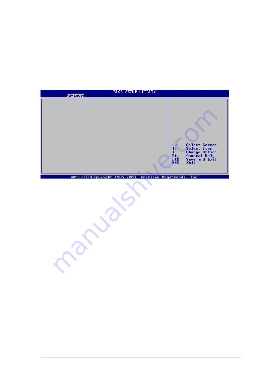
Onboard IEEE 1394 [Enabled]

Onboard IEEE 1394 [Enabled]

Onboard IEEE 1394 [Enabled]

Onboard IEEE 1394 [Enabled]

Onboard IEEE 1394 [Enabled]

Allows you to enable or disable the onboard IEEE 1394a controller.
Configuration options: [Enabled] [Disabled]

5.4.8

5.4.8

5.4.8

5.4.8

5.4.8

PCI Express Configuration

PCI Express Configuration

PCI Express Configuration

PCI Express Configuration

PCI Express Configuration

PCI Express Configuration

PCIE GFX Core Payload

[64 bytes]

NB-SB Link ASPM

[Disabled]

PCIE Wake Pin for S5

[Disabled]

PCIE GFX Core Payload [64 bytes]

PCIE GFX Core Payload [64 bytes]

PCIE GFX Core Payload [64 bytes]

PCIE GFX Core Payload [64 bytes]

PCIE GFX Core Payload [64 bytes]

Configuration options: [16 bytes] [32 bytes] [64 bytes]

NB-SB Link ASPM [Disabled]

NB-SB Link ASPM [Disabled]

NB-SB Link ASPM [Disabled]

NB-SB Link ASPM [Disabled]

NB-SB Link ASPM [Disabled]

Configuration options: [Disabled] [Enabled]

PCIE Wake Pin for S5 [Disabled]

PCIE Wake Pin for S5 [Disabled]

PCIE Wake Pin for S5 [Disabled]

PCIE Wake Pin for S5 [Disabled]

PCIE Wake Pin for S5 [Disabled]

Configuration options: [Disabled] [Enabled]

Summary of Contents for T2-AH1

Page 1: ...MODE Terminator 2 Barebone System Model T2 AH1 ...

Page 2: ...CONDITIONS OF MERCHANTABILITY OR FITNESS FOR A PARTICULAR PURPOSE IN NO EVENT SHALL ASUS ITS DIRECTORS OFFICERS EMPLOYEES OR AGENTS BE LIABLE FOR ANY INDIRECT SPECIAL INCIDENTAL OR CONSEQUENTIAL DAMAGES INCLUDING DAMAGES FOR LOSS OF PROFITS LOSS OF BUSINESS LOSS OF USE OR DATA INTERRUPTION OF BUSINESS AND THE LIKE EVEN IF ASUS HAS BEEN ADVISED OF THE POSSIBILITY OF SUCH DAMAGES ARISING FROM ANY DE...

Page 3: ...Basic Installation Basic Installation Basic Installation 2 1 Preparation 2 2 2 2 Before you proceed 2 2 2 3 Removing the cover 2 3 2 4 Removing the power supply 2 4 2 5 Installing a CPU 2 5 2 5 1 CPU installation 2 5 2 5 2 Installing the CPU fan and heatsink assembly 2 7 2 5 3 Removing the CPU fan and heatsink assembly 2 8 2 6 Installing a DIMM 2 9 2 6 1 Memory configurations 2 9 2 6 2 DIMM instal...

Page 4: ...l n Quiet Technology 3 15 3 4 6 ASUS PC Probe II 3 17 3 4 7 AC 97 audio feature 3 23 Chapter 4 Chapter 4 Chapter 4 Chapter 4 Chapter 4 Motherboard Info Motherboard Info Motherboard Info Motherboard Info Motherboard Info 4 1 Introduction 4 2 4 2 Motherboard layout 4 2 4 3 Jumper 4 3 4 4 Connectors 4 4 Chapter 5 Chapter 5 Chapter 5 Chapter 5 Chapter 5 BIOS Information BIOS Information BIOS Informati...

Page 5: ...18 5 4 3 LAN Cable Status 5 21 5 4 4 USB Configuration 5 22 5 4 5 CPU Configuration 5 23 5 4 6 Chipset 5 24 5 4 7 Onboard Devices Configuration 5 26 5 4 8 PCI Express Configuration 5 27 5 4 9 PCI PnP 5 28 5 5 Power menu 5 29 5 5 1 Suspend Mode 5 29 5 5 2 Repost Video on S3 Resume 5 29 5 5 3 ACPI 2 0 Support 5 29 5 5 4 ACPI APIC Support 5 29 5 5 5 APM Configuration 5 30 5 5 6 Hardware Monitor 5 32 ...

Page 6: ...ry to correct the interference by one or more of the following measures Reorient or relocate the receiving antenna Increase the separation between the equipment and receiver Connect the equipment to an outlet on a circuit different from that to which the receiver is connected Consult the dealer or an experienced radio TV technician for help Canadian Department of Communications Statement Canadian ...

Page 7: ...ay from connectors slots sockets and circuitry Avoid dust humidity and temperature extremes Do not place the product in any area where it may become wet Place the product on a stable surface If you encounter technical problems with the product contact a qualified service technician or your retailer Lithium Ion Battery Warning Lithium Ion Battery Warning Lithium Ion Battery Warning Lithium Ion Batt...

Page 8: ...ic installation Chapter 2 Basic installation Chapter 2 Basic installation This chapter provides step by step instructions on how to install components in the system 3 3 3 3 3 Chapter 3 Starting up Chapter 3 Starting up Chapter 3 Starting up Chapter 3 Starting up Chapter 3 Starting up This chapter helps you power up the system and install drivers and utilities from the support CD 4 4 4 4 4 Chapter ...

Page 9: ...completing a task Where to find more information Where to find more information Where to find more information Where to find more information Where to find more information Refer to the following sources for additional information and for product and software updates 1 1 1 1 1 ASUS Websites ASUS Websites ASUS Websites ASUS Websites ASUS Websites The ASUS websites worldwide provide updated informat...

Page 10: ...and heatsink assembly 2 x 5 25 drive bays 1 x 3 5 floppy disk drive bay 1 x 3 5 hard disk drive bay 6 x USB 2 0 ports 2 x IEEE 1394a ports 6 pin and 4 pin S PDIF In port S PDIF out port 7 in 1 storage card reader FM radio module and radio antenna LED panel Audio DJ play buttons 2 2 2 2 2 C a b l e s C a b l e s C a b l e s C a b l e s C a b l e s AC power cable Serial ATA cable Serial ATA power ca...

Page 11: ...H1 ASUS T2 AH1 ASUS T2 AH1 MODE Chapter 1 System introduction This chapter gives a general description of the ASUS T2 AH1 The chapter lists the system features including introduction on the front and rear panel and internal components ...

Page 12: ...9 with 1 GHz 800 MHz 400 MHz FSB and up to 2 GB system memory With audio functions extensive connectivity and Gigabit LAN capability the T2 AH1 is designed for the sophisticated With these and many more the T2 AH1 definitely delivers the cutting edge technology for your computing and multimedia needs 1 2 Front panel external The front panel includes the system and audio control buttons system LEDs...

Page 13: ...ard reader door Storage card reader door Storage card reader door Open this door to access the 7 in 1 storage card reader 10 10 10 10 10 LED panel LED panel LED panel LED panel LED panel The LED panel displays the audio medium CD FM radio frequency player status real time clock track number and time See page 1 10 for details The following front panel buttons are activated only when the system is i...

Page 14: ...vious audio track In Radio mode Radio mode Radio mode Radio mode Radio mode selects the previous preset station 16 16 16 16 16 NEXT button NEXT button NEXT button NEXT button NEXT button Press this button to perform various functions in different modes In CD mode CD mode CD mode CD mode CD mode selects the next audio track In Radio mode Radio mode Radio mode Radio mode Radio mode selects the next ...

Page 15: ...ck Memory Stick Memory Stick Memory Stick Memory Stick Pro card slot Memory Stick Pro card slot Memory Stick Pro card slot Memory Stick Pro card slot Memory Stick Pro card slot This slot is for a Memory Stick Memory Stick Pro storage card 23 23 23 23 23 SmartMedia SmartMedia SmartMedia SmartMedia SmartMedia card slot card slot card slot card slot card slot This slot is for a SmartMedia storage car...

Page 16: ...nnecting USB 2 0 devices such as a mouse printer scanner camera PDA and others 28 28 28 28 28 4 pin IEEE 1394a port 4 pin IEEE 1394a port 4 pin IEEE 1394a port 4 pin IEEE 1394a port 4 pin IEEE 1394a port This port provides high speed connectivity for IEEE 1394a compliant audio video devices storage peripherals and other PC devices 29 29 29 29 29 6 pin IEEE 1394a port 6 pin IEEE 1394a port 6 pin IE...

Page 17: ... keyboard port PS 2 keyboard port PS 2 keyboard port This purple 6 pin connector is for a PS 2 keyboard 6 6 6 6 6 VGA port VGA port VGA port VGA port VGA port This port connects a VGA monitor 7 7 7 7 7 Parallel port Parallel port Parallel port Parallel port Parallel port This 25 pin port connects a printer scanner or other devices 8 8 8 8 8 Line Out port Line Out port Line Out port Line Out port L...

Page 18: ...nt Chassis fan vent Chassis fan vent This vent is for the fan that provides ventilation inside the system chassis 17 17 17 17 17 S Video port S Video port S Video port S Video port S Video port black This port connects a television set with S Videofeature 18 18 18 18 18 Radio antenna port Radio antenna port Radio antenna port Radio antenna port Radio antenna port This port connects a radio antenna...

Page 19: ...stem when you remove the top cover and the power supply unit The installed components are labeled for your reference Proceed to Chapter 2 for instructions on installing additional system components 3 3 3 3 3 2 2 2 2 2 5 5 5 5 5 6 6 6 6 6 1 1 1 1 1 1 1 1 1 11 1 1 1 1 9 9 9 9 9 1 1 1 1 15 5 5 5 5 1 1 1 1 10 0 0 0 0 8 8 8 8 8 1 1 1 1 12 2 2 2 2 1 1 1 1 14 4 4 4 4 4 4 4 4 4 7 7 7 7 7 1 1 1 1 13 3 3 3 ...

Page 20: ...time Audio DJ mode Audio DJ mode Audio DJ mode Audio DJ mode Audio DJ mode The LED panel displays various information when the system is in Audio DJ mode In CD mode CD mode CD mode CD mode CD mode the LED panel displays the play pause icon number and duration of the audio CD track being played CD mode play paused status CD mode play paused status CD mode play paused status CD mode play paused stat...

Page 21: ...ASUS T2 AH1 ASUS T2 AH1 ASUS T2 AH1 ASUS T2 AH1 ASUS T2 AH1 MODE Chapter 2 Basic installation This chapter provides step by step instructions on how to install components in the system ...

Page 22: ...motherboard comes with an onboard standby power LED This LED lights up to indicate that the system is ON in sleep mode or in soft off mode and not powered OFF Unplug the power cable from the power outlet and make sure that the standby power LED is OFF before installing any system component 2 2 Before you proceed Take note of the following precautions before you install components into the system U...

Page 23: ...e disengaged from the chassis 4 Lift the cover then set aside 2 Use a Phillips screw driver to remove the cover screws Keep the screws for later use 2 3 Removing the cover To remove the cover 1 On the rear panel locate the three screws that secure the cover to the chassis 1 1 1 1 1 1 1 1 1 1 1 1 1 1 1 2 2 2 2 2 2 2 2 2 2 4 4 4 4 4 3 3 3 3 3 2 2 2 2 2 3 3 3 3 3 ...

Page 24: ...he PSU as the zoomed image shows until the side hook is disengaged from the chassis 5 Push the PSU towards the front panel for about half an inch 6 Slightly lift the PSU 2 4 Removing the power supply You must remove the power supply unit PSU before you can install a central processing unit CPU and other system components To remove the PSU 1 Lay the system on its side on a flat stable surface 2 Dis...

Page 25: ...of this processor can run applications faster than processors with only 32 bit or 64 bit wide data paths Take note of the marked corner with gold triangle on the CPU This mark should match a specific corner on the socket to ensure correct installation 2 5 1 2 5 1 2 5 1 2 5 1 2 5 1 CPU installation CPU installation CPU installation CPU installation CPU installation To install a CPU 1 Locate the CPU...

Page 26: ...does not fit in completely 3 Position the CPU above the socket such that the CPU corner with the gold triangle matches the socket corner with a small triangle 4 Carefully insert the CPU into the socket until it fits in place The CPU fits only in one correct orientation DO NOT force the CPU into the socket to prevent bending the pins and damaging the CPU 5 When the CPU is in place push down the soc...

Page 27: ...g and vacuum cover The CPU fan and heatsink assembly may be in the accessory box 2 Place the CPU fan and heatsink assembly on top of the installed CPU making sure it fits the retention module 3 Connect the CPU fan cable to the CPU fan connector on the motherboard 4 Align the metal clips to the side rail of the CPU fan and heatsink assembly with the locking levers in the reverse orientation 5 Snap ...

Page 28: ...the cable from the power source before removing the CPU fan and heatsink assembly To remove the CPU fan and heatsink assembly 1 Disconnect the CPU fan cable from the CPU fan connector on the motherboard 2 Carefully press down the locking lever 3 Unhook the end of the locking lever from the retention module hole 4 Slide out the metal clip to remove the hook of the other locking lever end from the r...

Page 29: ...MM in DIMM_A1 and DIMM_B1 If installing only one DDR DIMM install it in DIMM_A1 blue slot Always install DIMMs with the same CAS latency For optimum compatibility we recommend that you obtain memory modules from the same vendor Due to chipset resource allocation the system may detect less than your total system memory size when you enable the onboard VGA This motherboard does not support memory mo...

Page 30: ...368L6423FTN CCC SAMSUNG DS K4H560838F TCCC 3 512 MB SAMSUNG M368L6523BTM CCC SAMSUNG SS K4H510838B TCCC 3 256 MB MICRON MT8VDDT3264AG 40BCB MICRON SS MT46V32M8TG 5BC 512 MB MICRON MT16VDDT6464AG 40BCB MICRON DS MT46V32M8TG 5BC 256 MB Infineon HYS64D32300HU 5 C Infineon SS HYB25D256800CE 5C 3 512 MB Infineon HYS64D64320HU 5 C Infineon DS HYB25D256800CE 5C 256 MB Infineon HYS64D32301HU 5 C Infineon ...

Page 31: ...ynix SS HY5DU56822CT D43 3 512 MB A DATA MDOHY6F3H41Y0N1E0Z Hynix DS HY5DU56822CT D43 3 256 MB A DATA MDOAD5F3G31Y0D1E02 SS ADD8608A8A 5B 2 5 512 MB A DATA MDOAD5F3H41Y0D1E02 DS ADD8608A8A 5B 2 5 256 MB Winbond W9425GCDB 5 Winbond SS W942508CH 5 3 512 MB Winbond W9451GCDB 5 Winbond DS W942508CH 5 256 MB PSC AL5D8B53T 5B1K PSC SS A2S56D30BTP 2 5 512 MB PSC AL6D8B53T 5B1K PSC DS A2S56D30BTP 2 5 256 ...

Page 32: ...6804SCT5B 2 5 512 MB ProMOS V826664K24SCTG D0 DS V58C2256804SCT5B 2 5 256 MB Deutron AL5D8C53T 5B1T PSC SS A2S56D30CTP 2 5 512 MB Deutron AL6D8C53T 5B1T PSC DS A2S56D30CTP 2 5 256 MB GEIL GL5123200DC SS GL3LC32G88TG 35 512 MB GEIL GL1GB3200DC DS GL3LC32G88TG 35 256 MB GEIL GLX2563200UP SS GL3LC32G88TG 5A 256 MB GEIL GD3200 512DC SS WLCSP Package 256 MB crucial BL3264Z402 8TG Ballistix SS 2 512 MB ...

Page 33: ... 2 Unlock a socket by pressing the retaining clips outward 3 Align a DIMM on the socket such that the notch on the DIMM matches the break on the socket 4 Firmly insert the DIMM into the socket until the retaining clips snap back in place and the DIMM is properly seated A DDR DIMM is keyed with a notch so that it fits in only one direction DO NOT force a DIMM into a socket to avoid damaging the DIM...

Page 34: ...e to do so may cause you physical injury and damage the motherboard 2 7 1 2 7 1 2 7 1 2 7 1 2 7 1 Expansion slots Expansion slots Expansion slots Expansion slots Expansion slots PCI Express x16 slot PCI Express x16 slot PCI Express x16 slot PCI Express x16 slot PCI Express x16 slot This motherboard supports PCI Express x16 graphic cards that comply with PCI Express specifications The figure shows ...

Page 35: ...e card 2 Pull the expansion card lock to the direction of the arrow 3 Remove the metal cover opposite the slot that you intend to use 5 Replace the expansion card lock to secure the card to the chassis Expansion Expansion Expansion Expansion Expansion card lock card lock card lock card lock card lock Metal covers 3 P C I P C I P C I P C I P C I s l o t s l o t s l o t s l o t s l o t PCI Express P...

Page 36: ... Standard Function Standard Function Standard Function 0 System Timer 1 Keyboard Controller 2 Programmable Interrupt 4 Communications Port COM1 6 Floppy Disk Controller 7 Printer Port LPT1 8 System CMOS Real Time Clock 9 ACPI Mode when used 10 IRQ Holder for PCI Steering 11 IRQ Holder for PCI Steering 12 PS 2 Compatible Mouse Port 13 Numeric Data Processor 15 Secondary IDE Channel These IRQs are u...

Page 37: ... bottom hooks upward to release them from the metal tabs that secure them in place 4 Detach the front panel cover top hooks 5 Slightly push the front panel cover outward until it detaches from the chassis then set it aside 1 1 1 1 1 2 2 2 2 2 3 3 3 3 3 You may install a second optical drive only if you installed a Serial ATA hard disk drive Set your second optical drive as Slave device before conn...

Page 38: ...s on the power supply unit plugs 9 Connect the IDE ribbon cable to the IDE interface at the back of the optical drive matching the red stripe on the cable with Pin 1 on the IDE interface 10 Connect one end of the optical drive audio cable to the 4 pin connector at the back of the optical drive 11 Make sure that the other end of the IDE ribbon cable is connected to the IDE connector blue connector ...

Page 39: ...1 ASUS T2 AH1 ASUS T2 AH1 ASUS T2 AH1 ASUS T2 AH1 14 Lock the front panel cover hooks to the chassis holes as indicated 1 1 1 1 14 4 4 4 4 13 Reinstall the front panel cover by aligning its hooks with the chassis holes 1 1 1 1 13 3 3 3 3 ...

Page 40: ...an optical drive 2 Carefully insert the floppy disk drive into the floppy drive bay until the screw holes align with the holes on the bay 3 Secure the floppy disk drive with two screws 2 2 2 2 2 3 3 3 3 3 3 3 3 3 3 4 4 4 4 4 6 6 6 6 6 4 Connect the floppy disk drive signal cable to the signal connector at the back of the drive 5 Connect the other end of the signal cable to the floppy disk drive co...

Page 41: ... 1 Locate the HDD tray lock screw on the other side of the chassis 2 Remove the lock screw with a Philips screw driver Keep the screw for later use 4 Place a hard disk drive on the tray with its bottom on the open side Align the HDD and HDD tray screw holes 5 Secure the HDD with four screws 3 Slide the HDD tray outward until the tray slots are released from the chassis hooks 1 1 1 1 1 Tray locks T...

Page 42: ...cure the tray with the screw you removed earlier 8 Connect one end of the 40 pin IDE cable to the IDE connector on the drive 9 Connect a 4 pin power plug from the power supply unit to the HDD power connector See page 2 25 for details on the power supply unit plugs 10 Connect the other end of the IDE ribbon cable to the IDE connector blue connector labeled IDE on the motherboard See page 4 7 for th...

Page 43: ...g power plug power plug power plug If your Serial ATA HDD has both 4 pin and 15 pin connectors at the back use either the 15 pin SATA power adapter plug O R O R O R O R O R the legacy 4 pin power connector DO NOT DO NOT DO NOT DO NOT DO NOT use both to prevent damage to components and to keep the system from becoming unstable 3 For Serial ATA HDDs with a 4 pin power connector a Connect a 4 pin fem...

Page 44: ...lug to the ATX12V connector on the motherboard 2 Connect the 24 pin ATX power plug to the ATXPWR connector on the motherboard See page 4 6 for the location of power connectors 3 Position the PSU over the chassis 4 Align the PSU side hook with the metal slot located on the side of the optical drive bay 5 Slide the PSU toward the direction of the rear panel until it fits in place 6 Secure the PSU wi...

Page 45: ...r Voltage selector Voltage selector The PSU has a 115 V 230 V voltage selector switch located beside the power connector Use this switch to select the appropriate system input voltage according to the voltage supply in your area If the voltage supply in your area is 100 127 V set the switch to 115 V If the voltage supply in your area is 200 240 V set the switch to 230 V Setting the switch to 115 V...

Page 46: ...cover To replace the cover 1 Turn the chassis upright 2 Position the front edge of the cover at least two inches from the front panel cover Fit the cover tabs with the chassis rail and the front panel tabs 3 Lower the rear edge of the cover as shown 4 Push the cover slightly toward the front panel until it fits in place 2 3 4 5 5 Secure the cover with the three screws you removed earlier ...

Page 47: ...ASUS T2 AH1 ASUS T2 AH1 ASUS T2 AH1 ASUS T2 AH1 ASUS T2 AH1 MODE Chapter 3 Starting up This chapter helps you power up the system and install drivers and utilities from the support CD ...

Page 48: ...re MODE Press to put the system Press to put the system Press to put the system Press to put the system Press to put the system in Audio DJ mode in Audio DJ mode in Audio DJ mode in Audio DJ mode in Audio DJ mode Press to enter the Press to enter the Press to enter the Press to enter the Press to enter the system OS system OS system OS system OS system OS Because motherboard settings and hardware ...

Page 49: ...rivers to activate the devices ASUS InstAll Installation Wizard for Drivers ASUS InstAll Installation Wizard for Drivers ASUS InstAll Installation Wizard for Drivers ASUS InstAll Installation Wizard for Drivers ASUS InstAll Installation Wizard for Drivers Launches the ASUS InstallAll driver installation wizard AMD Cool n Quiet Driver AMD Cool n Quiet Driver AMD Cool n Quiet Driver AMD Cool n Quiet...

Page 50: ...ukon VCT Application Marvell Yukon VCT Application Marvell Yukon VCT Application Installs the Marvell Yukon Virtual Cable Tester VCT application The VCT is a cable diagnostic application that analyzes and reports LAN cable faults and shorts ULi Chipset Driver ULi Chipset Driver ULi Chipset Driver ULi Chipset Driver ULi Chipset Driver Installs the ULi Chipset driver Realtek Audio Driver Realtek Aud...

Page 51: ...application ASUS Radio Player Utility ASUS Radio Player Utility ASUS Radio Player Utility ASUS Radio Player Utility ASUS Radio Player Utility Installs the ASUS Radio Player application Adobe Acrobat Reader V7 0 Adobe Acrobat Reader V7 0 Adobe Acrobat Reader V7 0 Adobe Acrobat Reader V7 0 Adobe Acrobat Reader V7 0 The Acrobat Acrobat Reader software is for viewing files saved in Portable Document F...

Page 52: ...nu Make Disk menu Make Disk menu Make Disk menu The Make Disk Make Disk Make Disk Make Disk Make Disk menu allows you to create driver disks Make ULi 32 64bit SATA Driver Disk Make ULi 32 64bit SATA Driver Disk Make ULi 32 64bit SATA Driver Disk Make ULi 32 64bit SATA Driver Disk Make ULi 32 64bit SATA Driver Disk Allows you to create a ULi Serial ATA driver disk for a 32 64 bit system ...

Page 53: ... information Other information The icons on the top right side of the screen provide additional information on the motherboard and the contents of the support CD 3 3 5 3 3 5 3 3 5 3 3 5 3 3 5 ASUS contact information ASUS contact information ASUS contact information ASUS contact information ASUS contact information The Contact tab displays the ASUS contact information ...

Page 54: ... A U S A U S A U S A or Japan Japan Japan Japan Japan you must change the radio region in the BIOS setup to receive FM radio signals See section 5 4 1 Instant Music Configuration for details 3 4 Software information Most of the applications in the support CD have wizards that will conveniently guide you through the installation View the online help or readme file that came with the software for mo...

Page 55: ...e l C h a n n e l preset number to the radio station using the arrow buttons 4 Type the station name in the field then click O K O K O K O K O K 5 The stored channel is displayed in the preset station list 3 Another E d i t C h a n n e l E d i t C h a n n e l E d i t C h a n n e l E d i t C h a n n e l E d i t C h a n n e l window appears 4 Edit the station frequency and name Click O K O K O K O K...

Page 56: ... Configuration Instant Music Configuration menu select the item Instant Music Instant Music Instant Music Instant Music Instant Music and set it to Enabled Enabled Enabled Enabled Enabled See section 5 4 1 Instant Music Configuration 4 The Instant Music CD ROM Drive Instant Music CD ROM Drive Instant Music CD ROM Drive Instant Music CD ROM Drive Instant Music CD ROM Drive item appears if you enabl...

Page 57: ...r on the optical drive front panel 4 Insert an audio CD to the optical drive 5 Press Esc Esc Esc Esc Esc to turn on Instant Music 6 Press F1 F1 F1 F1 F1 or the Space Bar Space Bar Space Bar Space Bar Space Bar to play the first track on the audio CD 7 Refer to the Instant Music keyboard label to select other tracks or control the volume 8 Press F2 or Enter once to stop playing the audio CD Press F...

Page 58: ...an audio CD DVD To play an audio CD DVD 1 Insert an audio CD DVD to the optical drive 2 Press the PLAY PAUSE button to start playing the first track of the audio CD DVD 3 Press the NEXT or the PREVIOUS button to skip to the next track or to return to the previous track 4 Press the STOP button to stop playing the audio track Tuning into an FM radio station Tuning into an FM radio station Tuning int...

Page 59: ...io station press the PLAY PAUSE button for more than 2 seconds or until the station frequency display in the LED panel blinks 4 Use the NEXT button or the PREVIOUS button to select a preset number 1 9 for the selected station 5 Press the PLAY PAUSE button to assign the preset number to the radio station Adjusting the volume Adjusting the volume Adjusting the volume Adjusting the volume Adjusting t...

Page 60: ...ble Tester Using the Virtual Cable Tester Using the Virtual Cable Tester Using the Virtual Cable Tester Using the Virtual Cable Tester To use the the Marvell Virtual Cable Tester utility 1 Launch the VCT utility from the Windows desktop by clicking Start All Programs Marvell Virtual Cable Tester Start All Programs Marvell Virtual Cable Tester Start All Programs Marvell Virtual Cable Tester Start A...

Page 61: ...2 0 Support ACPI 2 0 Support ACPI 2 0 Support ACPI 2 0 Support ACPI 2 0 Support and set it to Y e s Y e s Y e s Y e s Y e s See section 5 5 Power Menu 4 Save your changes and exit BIOS Setup 5 Reboot your computer and set your Power Option Properties depending on your operating system The Cool n Quiet Technology item is set to Enabled by default in the BIOS Windows Windows Windows Windows Windows ...

Page 62: ...art Start Start Start button Select Programs ASUS Cool Quiet Cool Quiet Programs ASUS Cool Quiet Cool Quiet Programs ASUS Cool Quiet Cool Quiet Programs ASUS Cool Quiet Cool Quiet Programs ASUS Cool Quiet Cool Quiet 2 If you are using Windows XP click the Start Start Start Start Start button Select A l l A l l A l l A l l A l l Programs ASUS Cool Quiet Cool Quiet Programs ASUS Cool Quiet Cool Quie...

Page 63: ...PC Probe II ASUS PC Probe II ASUS PC Probe II ASUS PC Probe II ASUS PC Probe II 3 Follow the screen instructions to complete installation Launching PC Probe II Launching PC Probe II Launching PC Probe II Launching PC Probe II Launching PC Probe II You can launch the PC Probe II right after installation or anytime from the Windows desktop To launch the PC Probe II from the Windows desktop click Sta...

Page 64: ...Component Interconnect window Opens the Windows Management Instrumentation Windows Management Instrumentation Windows Management Instrumentation Windows Management Instrumentation Windows Management Instrumentation window Opens the hard disk drive memory CPU usage window Shows Hides the Preference Preference Preference Preference Preference section Minimizes the application Closes the application ...

Page 65: ...me Scheme Scheme options then select another position from the list box Click OK OK OK OK OK when finished Moving the monitor panels All monitor panels move together using a magnetic effect If you want to detach a monitor panel from the group click the horseshoe magnet icon You can now move or reposition the panel independently Adjusting the sensor threshold value You can adjust the sensor thresho...

Page 66: ...anagement Instrumentation browser This browser displays various Windows management information Click an item from the left panel to display on the right panel Click the plus sign before WMI Information WMI Information WMI Information WMI Information WMI Information to display the available information You can enlarge or reduce the browser size by dragging the bottom right corner of the browser DMI...

Page 67: ...the CPU hard disk drive space and memory usage Click to display the Usage browser CPU usage The CPU CPU CPU CPU CPU tab displays real time CPU usage in line graph representation If the CPU has an enabled Hyper Threading two separate line graphs display the operation of the two logical processors On Intel On Intel On Intel On Intel On Intel CPUs only CPUs only CPUs only CPUs only CPUs only Hard dis...

Page 68: ...s you to customize sensor alerts change temperature scale or enable the Q Fan feature Available on some motherboards only Available on some motherboards only Available on some motherboards only Available on some motherboards only Available on some motherboards only Loads the default Loads the default Loads the default Loads the default Loads the default threshold values threshold values threshold ...

Page 69: ...ng experience Installing the drivers and application Installing the drivers and application Installing the drivers and application Installing the drivers and application Installing the drivers and application To install the drivers and application 1 Place the support CD in the optical drive 2 When the drivers menu appears click Realtek Audio Realtek Audio Realtek Audio Realtek Audio Realtek Audio ...

Page 70: ...rs are installed into your system Using the AVRack Using the AVRack Using the AVRack Using the AVRack Using the AVRack Media Player Media Player Media Player Media Player Media Player Launching the AVRack Media Player A shortcut to the AVRack Media Player is automatically created on your desktop after you installed the audio drivers and application To launch the application simply double click the...

Page 71: ...ols controls controls controls controls Turn equalizer Turn equalizer Turn equalizer Turn equalizer Turn equalizer o n o n o n o n o n Preset options Preset options Preset options Preset options Preset options E l a p s e d E l a p s e d E l a p s e d E l a p s e d E l a p s e d recording time recording time recording time recording time recording time Stop recording Stop recording Stop recording ...

Page 72: ...3 26 3 26 3 26 3 26 3 26 Chapter 3 Starting up Chapter 3 Starting up Chapter 3 Starting up Chapter 3 Starting up Chapter 3 Starting up ...

Page 73: ...S T2 AH1 ASUS T2 AH1 ASUS T2 AH1 MODE Chapter 4 Motherboard info This chapter gives information about the motherboard that comes with the system This chapter includes the motherboard layout jumper settings and connector locations ...

Page 74: ...therboard for future upgrades or system reconfiguration 4 2 Motherboard layout CD ALC655 AUX Super I O Flash BIOS ATX12V BUZZER CLRTC IDE 24 89cm 9 8in 20 06cm 7 9in DDR DIMM_B1 64 128 bit 184 pin module DDR DIMM_A1 64 128 bit 184 pin module SB_PWR FP_AUDIO ULI M1573 EATXPWR SATA2 SATA1 USB12 PANEL LPT1 VGA Mic In Line In Line Out LAN_USB34 CPU_FAN ATI RS480 PCIEX16 PCI1 CHA_FAN Marvell 88E8053 VI...

Page 75: ...em passwords is powered by the onboard button cell battery To erase the RTC RAM 1 Turn OFF the computer and unplug the power cord 2 Remove the battery 3 Move the jumper cap from pins 1 2 default to pins 2 3 Keep the cap on pins 2 3 for about 5 10 seconds then move the cap back to pins 1 2 4 Re install the battery 5 Plug the power cord and turn ON the computer 6 Hold down the Del key during the boo...

Page 76: ...onnector on the front panel I O board A B 4 4 Connectors This section describes and illustrates the connectors on the motherboard See page 1 7 for the description of rear panel connectors 1 1 1 1 1 Front panel audio connector 10 1 pin FP_AUDIO Front panel audio connector 10 1 pin FP_AUDIO Front panel audio connector 10 1 pin FP_AUDIO Front panel audio connector 10 1 pin FP_AUDIO Front panel audio ...

Page 77: ...AN CPU and chassis fan connectors 3 pin CPU_FAN CPU and chassis fan connectors 3 pin CPU_FAN CPU and chassis fan connectors 3 pin CPU_FAN 3 pin CHA_FAN 3 pin CHA_FAN 3 pin CHA_FAN 3 pin CHA_FAN 3 pin CHA_FAN The fan connectors support the proprietary CPU fan and chassis fan Connect the fan cables to the fan connectors on the motherboard making sure that the black wire of each cable matches the gro...

Page 78: ...n the motherboard otherwise the system will not boot up 6 6 6 6 6 Floppy disk drive connector 34 1 pin FLOPPY Floppy disk drive connector 34 1 pin FLOPPY Floppy disk drive connector 34 1 pin FLOPPY Floppy disk drive connector 34 1 pin FLOPPY Floppy disk drive connector 34 1 pin FLOPPY This connector is for the provided floppy disk drive FDD signal cable Insert one end of the cable to this connecto...

Page 79: ...for the jumper settings Pin 20 on the IDE connector is removed to match the covered hole on the Ultra DMA cable connector This prevents incorrect insertion when you connect the IDE cable Use the 80 conductor IDE cable for Ultra DMA 100 66 IDE devices 8 8 8 8 8 Internal audio connectors 4 pin AUX CD Internal audio connectors 4 pin AUX CD Internal audio connectors 4 pin AUX CD Internal audio connect...

Page 80: ...nectors 7 pin SATA1 black Serial ATA connectors 7 pin SATA1 black Serial ATA connectors 7 pin SATA1 black Serial ATA connectors 7 pin SATA1 black Serial ATA connectors 7 pin SATA1 black SATA2 black SATA3 black SATA4 black SATA2 black SATA3 black SATA4 black SATA2 black SATA3 black SATA4 black SATA2 black SATA3 black SATA4 black SATA2 black SATA3 black SATA4 black These connectors are for the Seria...

Page 81: ...ystem power LED 1 pin PLED System power LED 1 pin PLED System power LED 1 pin PLED System power LED 1 pin PLED This 1 pin connector is for the system power LED The system power LED lights up when you turn on the system power and blinks when the system is in sleep mode Hard disk drive activity 1 pin HDLED Hard disk drive activity 1 pin HDLED Hard disk drive activity 1 pin HDLED Hard disk drive acti...

Page 82: ...4 10 4 10 4 10 4 10 4 10 Chapter 4 Motherboard info Chapter 4 Motherboard info Chapter 4 Motherboard info Chapter 4 Motherboard info Chapter 4 Motherboard info ...

Page 83: ...1 ASUS T2 AH1 ASUS T2 AH1 ASUS T2 AH1 ASUS T2 AH1 ASUS T2 AH1 MODE Chapter 5 BIOS setup This chapter tells how to change system settings through the BIOS Setup menus and describes the BIOS parameters ...

Page 84: ... to create a bootable floppy disk DOS environment a Insert a 1 44MB floppy disk into the drive b At the DOS prompt type format A S then press Enter Windows XP environment a Insert a 1 44 MB floppy disk to the floppy disk drive b Click Start Start Start Start Start from the Windows desktop then select M y M y M y M y M y Computer Computer Computer Computer Computer c Select the 3 1 2 Floppy Drive i...

Page 85: ...est BIOS file for the motherboard and rename the same to A8R4T ROM A8R4T ROM A8R4T ROM A8R4T ROM A8R4T ROM 2 Save the BIOS file to a floppy disk then restart the system 3 Press Alt F2 during POST to display the following EZFlash starting BIOS update Checking for floppy 4 Insert the floppy disk that contains the BIOS file to the floppy disk drive When the correct BIOS file is found EZ Flash perform...

Page 86: ...ess Enter The utility copies the current BIOS file to the floppy disk A afudos oOLDBIOS1 ROM AMI Firmware Update Utility Version 1 10 Copyright C 2002 American Megatrends Inc All rights reserved Reading flash done A 1 Copy the AFUDOS utility afudos exe from the motherboard support CD to the bootable floppy disk you created earlier 2 Boot the system in DOS mode then at the prompt type afudos o file...

Page 87: ...isit the ASUS website www asus com and download the latest BIOS file for the motherboard Save the BIOS file to a bootable floppy disk 4 The utility reads the file and starts updating the BIOS Do not shut down or reset the system while updating the BIOS to prevent system boot failure Write the BIOS filename on a piece of paper You need to type the exact BIOS filename at the DOS prompt A afudos iA8R...

Page 88: ...SUS CrashFree BIOS 2 utility ASUS CrashFree BIOS 2 utility The ASUS CrashFree BIOS 2 is an auto recovery tool that allows you to restore the BIOS file when it fails or gets corrupted during the updating process You can update a corrupted BIOS file using the motherboard support CD or the floppy disk that contains the updated BIOS file Recovering the BIOS from a floppy disk Recovering the BIOS from ...

Page 89: ...D ROM CD ROM found Reading file A8R4T ROM Completed Start flashing When no floppy disk is found the utility automatically checks the optical drive for the original or updated BIOS file The utility then updates the corrupted BIOS file Bad BIOS checksum Starting BIOS recovery Checking for floppy Bad BIOS checksum Starting BIOS recovery Checking for floppy 4 Restart the system after the utility compl...

Page 90: ...pdate Install ASUS Update Install ASUS Update Install ASUS Update VX XX XX VX XX XX VX XX XX VX XX XX VX XX XX See page 3 4 for the Utilities Utilities Utilities Utilities Utilities screen menu 3 The ASUS Update utility is copied to your system 5 1 5 5 1 5 5 1 5 5 1 5 5 1 5 ASUS Update utility ASUS Update utility ASUS Update utility ASUS Update utility ASUS Update utility The ASUS Update is a util...

Page 91: ...the BIOS through the Internet To update the BIOS through the Internet 1 Launch the ASUS Update utility from the Windows desktop by clicking Start Start Start Start Start Programs Programs Programs Programs Programs ASUS ASUS ASUS ASUS ASUS ASUSUpdate ASUSUpdate ASUSUpdate ASUSUpdate ASUSUpdate ASUSUpdate ASUSUpdate ASUSUpdate ASUSUpdate ASUSUpdate The ASUS Update main window appears 2 Select Updat...

Page 92: ...SUSUpdate ASUSUpdate ASUSUpdate ASUSUpdate ASUSUpdate ASUSUpdate ASUSUpdate ASUSUpdate The ASUS Update main window appears 2 Select Update BIOS from a Update BIOS from a Update BIOS from a Update BIOS from a Update BIOS from a file file file file file option from the drop down menu then click Next Next Next Next Next 4 From the FTP site select the BIOS version that you wish to download Click Next ...

Page 93: ...program Press Del during the Power On Self Test POST to enter the Setup utility otherwise POST continues with its test routines If you wish to enter Setup after POST restart the system by pressing Ctrl Alt Delete You can also restart by turning the system off and then back on Do this last option only if the first two failed The Setup program is designed to make it as easy to use as possible Being ...

Page 94: ...key on the keyboard until the desired item is highlighted Some of the navigation keys differ from one screen to another 5 2 3 5 2 3 5 2 3 5 2 3 5 2 3 Navigation keys Navigation keys Navigation keys Navigation keys Navigation keys At the bottom right corner of a menu screen are the navigation keys for that particular menu Use the navigation keys to select items in the menu and change the settings S...

Page 95: ...fer to 5 2 7 Pop up window 5 2 7 5 2 7 5 2 7 5 2 7 5 2 7 Pop up window Pop up window Pop up window Pop up window Pop up window Select a menu item then press Enter to display a pop up window with the configuration options for that item 5 2 8 5 2 8 5 2 8 5 2 8 5 2 8 Scroll bar Scroll bar Scroll bar Scroll bar Scroll bar A scroll bar appears on the right side of a menu screen when there are items tha...

Page 96: ... System Date Day xx xx xxxx System Date Day xx xx xxxx Allows you to set the system date 5 3 3 5 3 3 5 3 3 5 3 3 5 3 3 Legacy Diskette A 1 44M 3 5 in Legacy Diskette A 1 44M 3 5 in Legacy Diskette A 1 44M 3 5 in Legacy Diskette A 1 44M 3 5 in Legacy Diskette A 1 44M 3 5 in Sets the type of floppy drive installed Configuration options Disabled 360K 5 25 in 1 2M 5 25 in 720K 3 5 in 1 44M 3 5 in 2 88...

Page 97: ... N A if no IDE device is installed in the system Type Auto Type Auto Type Auto Type Auto Type Auto Selects the type of IDE drive Setting to Auto allows automatic selection of the appropriate IDE device type Select CDROM if you are specifically configuring a CD ROM drive Select ARMD ATAPI Removable Media Device if your device is either a ZIP LS 120 or MO drive Configuration options Not Installed Au...

Page 98: ...131 Build Date 07 15 05 Processor Type AMD Athlon tm 64 Processor 3200 Speed 2000 MHz Count 1 System Memory Size 192 MB PIO Mode Auto PIO Mode Auto PIO Mode Auto PIO Mode Auto PIO Mode Auto Selects the PIO mode Configuration options Auto 0 1 2 3 4 DMA Mode Auto DMA Mode Auto DMA Mode Auto DMA Mode Auto DMA Mode Auto Allows you to set the DMA mode Configuration options Auto SWDMA0 SWDMA1 SWDMA2 MWD...

Page 99: ...s Configuration PCI PnP 5 4 1 5 4 1 5 4 1 5 4 1 5 4 1 Instant Music Configuration Instant Music Configuration Instant Music Configuration Instant Music Configuration Instant Music Configuration Instant Music Disabled Instant Music Disabled Instant Music Disabled Instant Music Disabled Instant Music Disabled Enables or disables the Instant Music feature Setting this item to Enabled disables the pow...

Page 100: ...umperFree Configuration JumperFree Configuration JumperFree Configuration AI Overclocking Auto AI Overclocking Auto AI Overclocking Auto AI Overclocking Auto AI Overclocking Auto Allows you to select the overclocking options to achieve the desired CPU internal frequency Select either one of the preset overclocking configiuration options Manual Manual Manual Manual Manual allows you to individually...

Page 101: ...peed through the available preset values Configuration options Overclock 5 Overclock 10 Overclock 15 Overclock 20 Overclock 30 Support for overclock function depends on your system configuration ASUS does not guarantee this function for any system configuration The Overclock Options Overclock Options Overclock Options Overclock Options Overclock Options item appears only when the A I A I A I A I A...

Page 102: ...to set using one of the standard values Configuration options Auto Limit Memclock Value 100 MHz Memclock Value 100 MHz Memclock Value 100 MHz Memclock Value 100 MHz Memclock Value 100 MHz This item appears only if the Memclock Mode item is set to Limit Configuration options 100 MHz 133 MHz 166 MHz 183 MHz 200 MHz 216 MHz 233 MHz 250 MHz MCT Timing Mode Auto Allows you to set the MCT timing mode Co...

Page 103: ...h 1 2 Open 0 0M 3 6 Open 0 0M 4 5 Open 0 0M 7 8 Open 0 0M Check LAN cable during POST POST Check LAN Cable Disabled POST Check LAN Cable Disabled POST Check LAN Cable Disabled POST Check LAN Cable Disabled POST Check LAN Cable Disabled Allows you to enable or disable LAN cable check during system POST When enabled the menu reports the cable faults or shorts and displays the point length where the ...

Page 104: ...p from S5 Disabled USB Wake Up from S5 Disabled Allows you to enable or disable USB wake up from S5 When set to Enabled you need to unplug the USB device or plug in a USB device if none is plugged to avail of this function Configuration options Disabled Enabled USB 2 0 Controller Mode HiSpeed USB 2 0 Controller Mode HiSpeed USB 2 0 Controller Mode HiSpeed USB 2 0 Controller Mode HiSpeed USB 2 0 Co...

Page 105: ...ns Disabled Enabled MTRR Mapping Continuous MTRR Mapping Continuous MTRR Mapping Continuous MTRR Mapping Continuous MTRR Mapping Continuous This option determines the method used for programming CPU MTRRs when 4 GB or more of memory is present Discrete setting leaves the PCI hole below the 4 GB boundary undescribed Continuous explicitly descibes the PCI hole as non cacheable Configuration options ...

Page 106: ...d VGA Share Memory 64 MB Onboard VGA Share Memory 64 MB Onboard VGA Share Memory 64 MB Onboard VGA Share Memory 64 MB Configuration options 16MB 32MB 64MB 128MB GFX Clock Mode Sync GFX Clock Mode Sync GFX Clock Mode Sync GFX Clock Mode Sync GFX Clock Mode Sync GFX MemClock can be synchronous with HyperTransport Link clock o Asynchronous where it is derived from an external clock chip In Async mode...

Page 107: ...V Standard NTSC TV Standard NTSC TV Standard NTSC TV Standard NTSC Allows you to select the TV standard in your area Configuration options NTSC PAL PAL M PAL 60 NTSC JAP PAL CN PAL N Expansion Mode Disabled Expansion Mode Disabled Expansion Mode Disabled Expansion Mode Disabled Expansion Mode Disabled Allows you to enable or disable text and graphics expansion central mode selection Configuration ...

Page 108: ...on options Disabled 378 278 3BC AC 97 Audio Enabled AC 97 Audio Enabled AC 97 Audio Enabled AC 97 Audio Enabled AC 97 Audio Enabled Allows you to enable or disable the onboard AC 97 audio controller Configuration options Enabled Disabled Serial ATA Controller Enabled Serial ATA Controller Enabled Serial ATA Controller Enabled Serial ATA Controller Enabled Serial ATA Controller Enabled Allows you t...

Page 109: ...ration PCI Express Configuration PCIE GFX Core Payload 64 bytes NB SB Link ASPM Disabled PCIE Wake Pin for S5 Disabled PCIE GFX Core Payload 64 bytes PCIE GFX Core Payload 64 bytes PCIE GFX Core Payload 64 bytes PCIE GFX Core Payload 64 bytes PCIE GFX Core Payload 64 bytes Configuration options 16 bytes 32 bytes 64 bytes NB SB Link ASPM Disabled NB SB Link ASPM Disabled NB SB Link ASPM Disabled NB...

Page 110: ... No BIOS configures all the devices in the system When set to Yes and if you install a Plug and Play operating system the operating system configures the Plug and Play devices not required for boot Configuration options No Yes PCI Latency Timer 64 PCI Latency Timer 64 PCI Latency Timer 64 PCI Latency Timer 64 PCI Latency Timer 64 Allows you to select the value in units of PCI clocks for the PCI de...

Page 111: ...PI 2 0 Support No ACPI 2 0 Support No Allows you to add more tables for Advanced Configuration and Power Interface ACPI 2 0 specifications Configuration options No Yes 5 5 4 5 5 4 5 5 4 5 5 4 5 5 4 ACPI APIC Support Enabled ACPI APIC Support Enabled ACPI APIC Support Enabled ACPI APIC Support Enabled ACPI APIC Support Enabled Allows you to enable or disable the Advanced Configuration and Power Int...

Page 112: ...Restore on AC Power Loss Power Off When set to Power Off the system goes into off state after an AC power loss When set to Power On the system goes on after an AC power loss When set to Last State the system goes into either off or on state whatever the system state was before the AC power loss Configuration options Power Off Power On Last State Power On By PS 2 Keyboard Disabled Power On By PS 2 ...

Page 113: ... either settings of Enabled or Disabled for powering up the computer when the external modem receives a call while the computer is in Soft off mode Configuration options Disabled Enabled The computer cannot receive or transmit data until the computer and applications are fully running Thus connection cannot be made on the first try Turning an external modem off and then back on while the computer ...

Page 114: ...eed xxxxRPM N A or Ignored The onboard hardware monitor automatically detects and displays the CPU fan speed in rotations per minute RPM If the fan is not connected to the motherboard the field shows N A Chassis Fan Speed xxxxRPM N A or Ignored Chassis Fan Speed xxxxRPM N A or Ignored Chassis Fan Speed xxxxRPM N A or Ignored Chassis Fan Speed xxxxRPM N A or Ignored Chassis Fan Speed xxxxRPM N A or...

Page 115: ...Floppy Drive 1st xxth Boot Device 1st Floppy Drive 1st xxth Boot Device 1st Floppy Drive 1st xxth Boot Device 1st Floppy Drive These items specify the boot device priority sequence from the available devices The number of device items that appears on the screen depends on the number of devices installed in the system Configuration options xxxxx Drive Disabled Boot Device Priority 1st Boot Device 1...

Page 116: ...e BIOS Sets the display mode for option ROM Configuration options Force BIOS Keep Current Bootup Num Lock On Bootup Num Lock On Bootup Num Lock On Bootup Num Lock On Bootup Num Lock On Allows you to select the power on state for the NumLock Configuration options Off On PS 2 Mouse Support Auto PS 2 Mouse Support Auto PS 2 Mouse Support Auto PS 2 Mouse Support Auto PS 2 Mouse Support Auto Allows you...

Page 117: ...t this item to set or change the supervisor password The Supervisor Password item on top of the screen shows the default Not Installed Not Installed Not Installed Not Installed Not Installed After you set a password this item shows Installed Installed Installed Installed Installed To set a Supervisor Password 1 Select the Change Supervisor Password item and press Enter 2 From the password box type...

Page 118: ...s viewing and changing all the fields in the Setup utility Change User Password Change User Password Change User Password Change User Password Change User Password Select this item to set or change the user password The User Password item on top of the screen shows the default Not Installed Not Installed Not Installed Not Installed Not Installed After you set a password this item shows Installed I...

Page 119: ... Check Setup When set to Setup BIOS checks for user password when accessing the Setup utility When set to Always BIOS checks for user password both when accessing Setup and booting the system Configuration options Setup Always 5 7 Exit menu Pressing Esc does not immediately exit this menu Select one of the options from this menu or F10 from the legend bar to exit The Exit menu items allow you to l...

Page 120: ...ts Load Setup Defaults This option allows you to load the default values for each of the parameters on the Setup menus When you select this option or if you press F5 a confirmation window appears Select Ok Ok Ok Ok Ok to load default values Select Exit Save Changes Exit Save Changes Exit Save Changes Exit Save Changes Exit Save Changes or make other changes before saving the values to the non vola...

Page 121: ...ASUS T2 AH1 ASUS T2 AH1 ASUS T2 AH1 ASUS T2 AH1 ASUS T2 AH1 MODE Appendix Appendix The Appendix includes the power supply unit specification for this system ...

Page 122: ...ic Current Harmonic Current Harmonic Current Harmonic Meets EN61000 3 2 100 Vac 50 Hz or 230 Vac 50 Hz at full load E P A E P A E P A E P A E P A 50 min at input 115 Vac 60 Hz Output characteristics Output characteristics Output characteristics Output characteristics Output characteristics O u t p u t O u t p u t O u t p u t O u t p u t O u t p u t Load Range Load Range Load Range Load Range Load ...

Reviews: