


ROG STRIX Z270G GAMING
1-11
C
h
ap
te
r
1
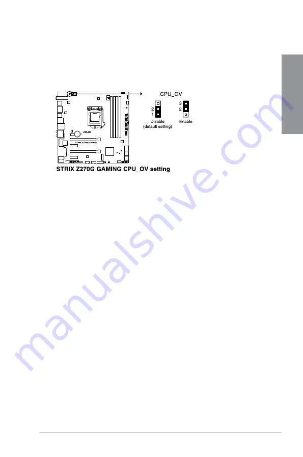
2.
CPU Over Voltage jumper (3-pin CPU_OV)
The CPU Over Voltage jumper allows you to set a higher CPU voltage for a exible
overclocking system, depending on the type of the installed CPU. To gain more CPU
voltage setting, insert the jumper to pins 2-3. To go back to its default CPU voltage
setting, insert the jumper to pins 1-2.
Summary of Contents for STRIX Z270G GAMING
Page 1: ...Motherboard STRIX Z270G GAMING ...
Page 16: ...xvi ...
Page 18: ...1 2 Chapter 1 Product Introduction Chapter 1 1 1 2 Motherboard layout ...
Page 38: ...1 22 Chapter 1 Product Introduction Chapter 1 ...
Page 44: ...2 6 Chapter 2 Basic Installation Chapter 2 To uninstall the CPU heatsink and fan assembly ...
Page 45: ...ROG STRIX Z270G GAMING 2 7 Chapter 2 To remove a DIMM 2 1 4 DIMM installation ...
Page 47: ...ROG STRIX Z270G GAMING 2 9 Chapter 2 2 1 6 SATA device connection OR ...
Page 51: ...ROG STRIX Z270G GAMING 2 13 Chapter 2 2 1 9 M 2 installation ...
Page 60: ...2 22 Chapter 2 Basic Installation Chapter 2 ...
Page 106: ...A 8 Appendix Appendix ...