2-36
Chapter 2: Hardware information
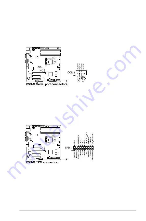
8. Serial port connectors (10-1 pin COM2)
These connectors are for the serial COM2 port. Connect the serial port
module cable to one of these connectors, then install the module to a slot
opening at the back of the system chassis.
9. Trusted Platform Module connector (20-1 pin TPM1)
This connector supports a Trusted Platform Module (TPM) system, which can
securely store keys, digital certificates, passwords, and data. A TPM system
also helps enhance network security, protects digital identities, and ensures
platform integrity.
Summary of Contents for P9D-M Series
Page 1: ...Motherboard P9D M Series ...
Page 14: ...xiv ...
Page 15: ...Chapter 1 Product Introduction ...
Page 21: ...Chapter 2 Hardware Information ...
Page 25: ...ASUS P9D M Series 2 5 2 2 3 Motherboard layout P9D M Motherboard Layout ...
Page 26: ...2 6 Chapter 2 Hardware information V P9D MV Motherboard Layout ...
Page 27: ...ASUS P9D M Series 2 7 1 X P9D MX Motherboard Layout ...
Page 60: ...2 40 Chapter 2 Hardware information ...
Page 61: ...Chapter 3 Powering Up ...
Page 65: ...Chapter 4 BIOS setup ...
Page 104: ...4 40 Chapter 4 BIOS setup ...
Page 105: ...Chapter 5 RAID Configuration ...
Page 123: ...Chapter 6 Driver installation ...
Page 151: ...Appendix A Reference Information ...
Page 153: ...ASUS P9D M Series A 3 A 1 P9D M block diagram A 2 P9D MV block diagram ...
Page 154: ...A 4 Appendix A Reference information A 3 P9D MX block diagram ...


