background image

4 - 3 6

4 - 3 6

4 - 3 6

4 - 3 6

4 - 3 6

C h a p t e r   4 :   B I O S   s e t u p

C h a p t e r   4 :   B I O S   s e t u p

C h a p t e r   4 :   B I O S   s e t u p

C h a p t e r   4 :   B I O S   s e t u p

C h a p t e r   4 :   B I O S   s e t u p

4.6.2

4.6.2

4.6.2

4.6.2

4.6.2

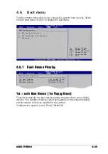
Boot Settings Configuration

Boot Settings Configuration

Boot Settings Configuration

Boot Settings Configuration

Boot Settings Configuration

Boot Settings Configuration

Quick Boot

[Enabled]

Full Screen Logo

[Enabled]

AddOn ROM Display Mode

[Force BIOS]

Bootup Num-Lock

[On]

PS/2 Mouse Support

[Auto]

Wait For ‘F1’ If Error

[Enabled]

Hit ‘DEL’ Message Display

[Enabled]

Interrupt 19 Capture

[Disabled]

Allows BIOS to skip
certain tests while
booting. This will
decrease the time
needed to boot the
system.

Set this item to [Enabled] to use the ASUS MyLogo™ feature.

Quick Boot [Enabled]

Quick Boot [Enabled]

Quick Boot [Enabled]

Quick Boot [Enabled]

Quick Boot [Enabled]

Enabling this item allows the BIOS to skip some power on self tests (POST)
while booting to decrease the time needed to boot the system. When set
to [Disabled], BIOS performs all the POST items.
Configuration options: [Disabled] [Enabled]

Full Screen Logo [Enabled]

Full Screen Logo [Enabled]

Full Screen Logo [Enabled]

Full Screen Logo [Enabled]

Full Screen Logo [Enabled]

This allows you to enable or disable the full screen logo display feature.
Configuration options: [Disabled] [Enabled]

Add On ROM Display Mode [Force BIOS]

Add On ROM Display Mode [Force BIOS]

Add On ROM Display Mode [Force BIOS]

Add On ROM Display Mode [Force BIOS]

Add On ROM Display Mode [Force BIOS]

Sets the display mode for option ROM.
Configuration options: [Force BIOS] [Keep Current]

Bootup Num-Lock [On]

Bootup Num-Lock [On]

Bootup Num-Lock [On]

Bootup Num-Lock [On]

Bootup Num-Lock [On]

Allows you to select the power-on state for the NumLock.
Configuration options: [Off] [On]

PS/2 Mouse Support [Auto]

PS/2 Mouse Support [Auto]

PS/2 Mouse Support [Auto]

PS/2 Mouse Support [Auto]

PS/2 Mouse Support [Auto]

Allows you to enable or disable support for PS/2 mouse.
Configuration options: [Disabled] [Enabled] [Auto]

Wait for ‘F1’ If Error [Enabled]

Wait for ‘F1’ If Error [Enabled]

Wait for ‘F1’ If Error [Enabled]

Wait for ‘F1’ If Error [Enabled]

Wait for ‘F1’ If Error [Enabled]

When set to Enabled, the system waits for the F1 key to be pressed when
error occurs. Configuration options: [Disabled] [Enabled]

Summary of Contents for P5P800

Page 1: ...Motherboard P5P800 ...

Page 2: ...OR AGENTS BE LIABLE FOR ANY INDIRECT SPECIAL INCIDENTAL OR CONSEQUENTIAL DAMAGES INCLUDING DAMAGES FOR LOSS OF PROFITS LOSS OF BUSINESS LOSS OF USE OR DATA INTERRUPTION OF BUSINESS AND THE LIKE EVEN IF ASUS HAS BEEN ADVISED OF THE POSSIBILITY OF SUCH DAMAGES ARISING FROM ANY DEFECT OR ERROR IN THIS MANUAL OR PRODUCT SPECIFICATIONS AND INFORMATION CONTAINED IN THIS MANUAL ARE FURNISHED FOR INFORMAT...

Page 3: ...ve ASUS features 1 4 Chapter 2 Hardware information Chapter 2 Hardware information Chapter 2 Hardware information Chapter 2 Hardware information Chapter 2 Hardware information 2 1 Before you proceed 2 1 2 2 Motherboard overview 2 2 2 2 1 Placement direction 2 2 2 2 2 Screw holes 2 2 2 2 3 Motherboard layout 2 3 2 2 4 Layout Contents 2 4 2 3 Central Processing Unit CPU 2 6 2 3 1 Installling the CPU...

Page 4: ...apter 4 BIOS setup Chapter 4 BIOS setup Chapter 4 BIOS setup Chapter 4 BIOS setup Chapter 4 BIOS setup 4 1 Managing and updating your BIOS 4 1 4 1 1 Creating a bootable floppy disk 4 1 4 1 2 ASUS EZ Flash utility 4 2 4 1 3 AFUDOS utility 4 3 4 1 4 ASUS CrashFree BIOS 2 utility 4 5 4 1 5 ASUS Update utility 4 7 4 2 BIOS setup program 4 10 4 2 1 BIOS menu screen 4 11 4 2 2 Menu bar 4 11 4 2 3 Naviga...

Page 5: ...0 4 5 2 Repost Video on S3 Resume 4 30 4 5 3 ACPI 2 0 Support 4 30 4 5 4 ACPI APIC Support 4 30 4 5 5 APM Configuration 4 31 4 5 6 Hardware Monitor 4 33 4 6 Boot menu 4 35 4 6 1 Boot Device Priority 4 35 4 6 2 Boot Settings Configuration 4 36 4 6 3 Security 4 37 4 7 Exit menu 4 40 Chapter 5 Software support Chapter 5 Software support Chapter 5 Software support Chapter 5 Software support Chapter 5 ...

Page 6: ...v i v i v i v i v i 5 3 1 ASUS MyLogo 5 7 5 3 2 ASUS Instant Music 5 9 5 3 3 AI NET 2 5 11 Using the Virtual Cable Tester 5 11 5 3 4 AI Audio 5 12 Contents ...

Page 7: ...e user is encouraged to try to correct the interference by one or more of the following measures Reorient or relocate the receiving antenna Increase the separation between the equipment and receiver Connect the equipment to an outlet on a circuit different from that to which the receiver is connected Consult the dealer or an experienced radio TV technician for help Canadian Department of Communica...

Page 8: ... correct voltage in your area If you are not sure about the voltage of the electrical outlet you are using contact your local power company If the power supply is broken do not try to fix it by yourself Contact a qualified service technician or your retailer Operation safety Operation safety Operation safety Operation safety Operation safety Before installing the motherboard and adding devices on ...

Page 9: ...ST messages and ways of shutting down the system Chapter 4 BIOS setup Chapter 4 BIOS setup Chapter 4 BIOS setup Chapter 4 BIOS setup Chapter 4 BIOS setup This chapter tells how to change system settings through the BIOS Setup menus Detailed descriptions of the BIOS parameters are also provided Chapter 5 Software support Chapter 5 Software support Chapter 5 Software support Chapter 5 Software suppo...

Page 10: ...s and additional information to help you complete a task IMPORTANT IMPORTANT IMPORTANT IMPORTANT IMPORTANT Instructions that you MUST follow to complete a task Bold text Bold text Bold text Bold text Bold text Indicates a menu or an item to select Italics Used to emphasize a word or a phrase Key Keys enclosed in the less than and greater than sign means that you must press the enclosed key Example...

Page 11: ...ge Intel 865PE Southbridge Intel ICH5 800 533 MHz Dual channel memory architecture 4 x 184 pin DIMM sockets support unbufferred non ECC 400 333 266 MHz DDR memory modules 1 x AGP 8X graphics card slot 5 x PCI slots Intel ICH5 Southbridge supports 2 x Ultra DMA 100 66 33 2 x Serial ATA hard disk drives ADI AD1985 audio solution with 5 1 channel CODEC SoundBlaster Live upgradable Audio Sensing Techn...

Page 12: ...5 port 4 x USB 2 0 ports 1 x S PDIF out port 1 x PS 2 keyboard port 1 x PS 2 mouse port 6 channel audio ports 1 x Floppy disk drive connector 2 x IDE connectors 2 x Serial ATA connectors 1 x CPU fan connector 1 x Chassis fan connector 1 x Serial port 2 connector COM2 port 1 x 24 pin ATX power connector 1 x 4 pin ATX 12 V power connector 2 x USB 2 0 connectors for 4 additional USB 2 0 ports 1 x CD ...

Page 13: ...1 Product introduction This chapter describes the motherboard features and the new technologies it supports ...

Page 14: ...ASUS P5P800 ASUS P5P800 ASUS P5P800 ASUS P5P800 ASUS P5P800 Chapter summary 1 1 Welcome 1 1 1 2 Package contents 1 1 1 3 Special features 1 2 ...

Page 15: ...ackage with the list below 1 2 Package contents Check your motherboard package for the following items Motherboard Motherboard Motherboard Motherboard Motherboard ASUS P5P800 motherboard I O modules I O modules I O modules I O modules I O modules USB 2 0 2 ports and GAME 1 port module Cables Cables Cables Cables Cables 2 x Serial ATA signal cables 1 x Ultra DMA 100 66 cable 40 conductor IDE cable ...

Page 16: ... support Dual channel DDR400 memory support Dual channel DDR400 memory support Employing the Double Data Rate DDR memory technology the motherboard supports up to 4GB of system memory using DDR400 333 266 DIMMs The ultra fast 400MHz memory bus delivers the required bandwidth for the latest 3D graphics multimedia and Internet applications Serial ATA technology Serial ATA technology Serial ATA techn...

Page 17: ...1 and 2 29 for details Temperature fan and voltage monitoring Temperature fan and voltage monitoring Temperature fan and voltage monitoring Temperature fan and voltage monitoring Temperature fan and voltage monitoring The CPU temperature is monitored by the ASIC integrated in the Winbond Super I O to prevent overheating and damage The system fan rotations per minute RPM is monitored for timely fai...

Page 18: ...hnology smartly adjusts the CPU fan speed according to the system loading to ensure quiet cool and efficient operation See page 4 33 for details ASUS Multi language BIOS ASUS Multi language BIOS ASUS Multi language BIOS ASUS Multi language BIOS ASUS Multi language BIOS The multi language BIOS allows you to select the language of your choice from the available options The localized BIOS menus allow...

Page 19: ... Hardware information This chapter lists the hardware setup procedures that you have to perform when installing system components It includes description of the jumpers and connectors on the motherboard ...

Page 20: ...SUS P5P800 ASUS P5P800 ASUS P5P800 Chapter summary 2 1 Before you proceed 2 1 2 2 Motherboard overview 2 2 2 3 Central Processing Unit CPU 2 6 2 4 System memory 2 11 2 5 Expansion slots 2 15 2 6 Jumpers 2 20 2 7 Connectors 2 23 ...

Page 21: ...tricity Hold components by the edges to avoid touching the ICs on them Whenever you uninstall any component place it on a grounded antistatic pad or in the bag that came with the component Before you install or remove any component ensure Before you install or remove any component ensure Before you install or remove any component ensure Before you install or remove any component ensure Before you ...

Page 22: ...2 2 1 2 2 1 2 2 1 2 2 1 2 2 1 Placement direction Placement direction Placement direction Placement direction Placement direction When installing the motherboard make sure that you place it into the chassis in the correct orientation The edge with external ports goes to the rear part of the chassis as indicated in the image below 2 2 2 2 2 2 2 2 2 2 2 2 2 2 2 Screw holes Screw holes Screw holes Sc...

Page 23: ...ine Out Top Line In Accelerated Graphics Port AGP FP_AUDIO AD1985 USB2 0 T USB3 B USB4 Top RJ 45 GAME ATX12V CHASSIS DDR DIMM_B1 64 bit 184 pin module PCI2 PCI3 PCI4 PCI5 CLRTC FLOPPY PRI_IDE PARALLEL PORT COM1 SPDIF_O SPDIF_OUT EATXPWR DDR DIMM_A1 64 bit 184 pin module DDR DIMM_A2 64 bit 184 pin module DDR DIMM_B2 64 bit 184 pin module KBPWR CHA_FAN1 Intel ICH5 Intel 82865PE Memory Controller Hub...

Page 24: ...t 2 19 Jumpers Jumpers Jumpers Jumpers Jumpers P a g e P a g e P a g e P a g e P a g e 1 Clear RTC RAM 3 pin CLRTC 2 20 2 USB Device wake up 3 pin USBPW12 USBPW34 USBPW56 USBPW78 2 21 3 Keyboard power 3 pin KBPWR 2 22 Rear panel connectors Rear panel connectors Rear panel connectors Rear panel connectors Rear panel connectors P a g e P a g e P a g e P a g e P a g e 1 PS 2 mouse port 2 23 2 Paralle...

Page 25: ... 2 28 7 Digital audio connector 4 1 pin SPDIF_OUT 2 28 8 Serial port 2 connector 10 1 pin COM2 2 29 9 USB headers 10 1 USB56 USB78 2 29 10 ATX power connector 24 pin EATXPWR 2 30 11 ATX 12V power connector 4 pin ATX12V 2 30 12 Optical audio connector 4 pin CD 2 31 13 Auxilliary audio connector 4 pin AUX 2 31 14 GAME MIDI connector 16 1 pin GAME 2 31 15 Chassis intrusion connector 4 1 pin CHASSIS 2...

Page 26: ...in this section do not match the CPU documentation follow the latter Upon purchase of the motherboard make sure that the PnP cap is on the socket and the socket pins are not bent Contact your retailer immediately if the PnP cap is missing or if you see any damage to the PnP cap socket pins motherboard components ASUS will shoulder the cost of repair only if the damage is shipment transit related K...

Page 27: ...nto the CPU notch Alignment key Alignment key Alignment key Alignment key Alignment key Gold triangle mark Gold triangle mark Gold triangle mark Gold triangle mark Gold triangle mark Load plate Load plate Load plate Load plate Load plate A B 2 Press the load lever with your thumb A and move it to the left B until it is released from the retention tab Retention tab Retention tab Retention tab Reten...

Page 28: ...gy is supported under Windows XP 2003 Server and Linux 2 4 x kernel and later versions only Under Linux use the Hyper Threading compiler to compile the code If you are using any other operating systems disable the Hyper Threading Technology item in the BIOS to ensure system stability and performance Installing Windows XP Service Pack 1 is recommended Make sure to enable the Hyper Threading Technol...

Page 29: ...n and heatsink assembly If you buy a CPU separately make sure that you use only Intel certified multi directional heatsink and fan Your Intel Pentium 4 LGA775 heatsink and fan assembly comes in a push pin design and requires no tool to install If you purchased a separate CPU heatsink and fan assembly make sure that a Thermal Interface Material is properly applied to the CPU heatsink or CPU before ...

Page 30: ...an connector Hardware monitoring errors can occur if you fail to plug this connector 3 When the fan and heatsink assembly is in place connect the CPU fan cable to the connector on the motherboard labeled CPU_FAN 2 Push down two fasteners at a time in a diagonal sequence to secure the heatsink and fan assembly in place A A B B B B A A P5P800 R P5P800 CPU Fan connector CPU_FAN GND CPU FAN PWR CPU FA...

Page 31: ...g the CPU heatsink and fan Uninstalling the CPU heatsink and fan Uninstalling the CPU heatsink and fan To uninstall the CPU heatsink and fan 1 Disconnect the CPU fan cable from the connector on the motherboard labeled CPU_FAN1 2 Rotate each fastener counterclockwise 3 Pull up two fasteners at a time in a diagonal sequence to disengage the heatsink and fan assembly from the motherboard A A B B B B ...

Page 32: ... 2 Hardware information Chapter 2 Hardware information Chapter 2 Hardware information 4 Remove the heatsink and fan assembly from the motherboard 5 Rotate each fastener clockwise to reset the orientation When reset each fastener should be oriented as shown with the narrow groove directed outward ...

Page 33: ...s Important notes Important notes Important notes Use the blue DIMM slots first Make sure to unplug the power supply before adding or removing DIMMs or other system components Failure to do so may cause severe damage to both the motherboard and the components 1 For optimum compatibility it is recommended that you obtain memory modules from the same vendor See the DDR400 Qualified Vendor List QVL o...

Page 34: ...b l u e black black black black black Single channel 1 Populated 2 Populated 3 Populated 4 Populated Dual channel 1 Populated Populated 2 Populated Populated 3 Populated Populated Populated Populated C P U F S B C P U F S B C P U F S B C P U F S B C P U F S B DDR DIMM Type DDR DIMM Type DDR DIMM Type DDR DIMM Type DDR DIMM Type Memory Frequency Memory Frequency Memory Frequency Memory Frequency Me...

Page 35: ...ATA MDOSS6F3G31Y0K1E0Z SAMSUNG SS K4H560838E TCCC 512MB A DATA MDOSS6F3H41Y0N1E0Z SAMSUNG DS K4H560838F TCCC 256MB A DATA MDOHY6F3G31Y0N1E0Z Hynix SS HY5DU56822CT D43 512MB A DATA MDOHY6F3H41Y0N1E0Z Hynix DS HY5DU56822CT D43 256MB A DATA MDOAD5F3G31Y0D1E02 N A SS ADD8608A8A 5B 512MB A DATA MDOAD5F3H41Y0D1E02 N A DS ADD8608A8A 5B 256MB Winbond W9425GCDB 5 Winbond SS W942508CH 5 512MB Winbond W9451G...

Page 36: ...til the retaining clips snap back in place and the DIMM is properly seated 1 Unlock a DIMM socket by pressing the retaining clips outward 2 Align a DIMM on the socket such that the notch on the DIMM matches the break on the socket Locked Retaining Clip Locked Retaining Clip Locked Retaining Clip Locked Retaining Clip Locked Retaining Clip Make sure to unplug the power supply before adding or remov...

Page 37: ... that you intend to use Keep the screw for later use 4 Align the card connector with the slot and press firmly until the card is completely seated on the slot 5 Secure the card to the chassis with the screw you removed earlier 6 Replace the system cover 2 5 2 2 5 2 2 5 2 2 5 2 2 5 2 Configuring an expansion card Configuring an expansion card Configuring an expansion card Configuring an expansion c...

Page 38: ...ime Clock 9 4 IRQ holder for PCI steering 10 5 IRQ holder for PCI steering 11 6 IRQ holder for PCI steering 12 7 PS 2 Compatible Mouse Port 13 8 Numeric Data Processor 14 9 Primary IDE Channel 15 10 Secondary IDE Channel These IRQs are usually available for ISA or PCI devices IRQ assignments for this motherboard IRQ assignments for this motherboard IRQ assignments for this motherboard IRQ assignme...

Page 39: ...installed on a PCI slot 2 5 5 2 5 5 2 5 5 2 5 5 2 5 5 AGP slot AGP slot AGP slot AGP slot AGP slot The Accelerated Graphics Port AGP slot supports AGP8X 4X cards When you buy an AGP card make sure that you ask for one with 1 5V specification Note the notches on the card golden fingers to ensure that they fit the AGP slot on your motherboard Install only 1 5 V or 0 8 V AGP cards on this motherboard...

Page 40: ... the computer and unplug the power cord 2 Remove the onboard battery 3 Move the jumper cap from pins 1 2 default to pins 2 3 Keep the cap on pins 2 3 for about 5 10 seconds then move the cap back to pins 1 2 4 Re install the battery 5 Plug the power cord and turn ON the computer 6 Hold down the Del key during the boot process and enter BIOS setup to re enter data Except when clearing the RTC RAM n...

Page 41: ...g the connected USB devices Set to 5VSB to wake up from S3 and S4 sleep modes no power to CPU DRAM in slow refresh power supply in reduced power mode The USBPWR12 and USBPWR34 jumpers are for the rear USB ports The USBPWR56 and USBPWR78 jumper is for the internal USB connectors that you can connect to additional USB ports The USB device wake up feature requires a power supply that can provide 500m...

Page 42: ...n KBPWR Keyboard power 3 pin KBPWR Keyboard power 3 pin KBPWR This jumper allows you to enable or disable the keyboard wake up feature Set this jumper to pins 2 3 5VSB if you wish to wake up the computer when you press a key on the keyboard the default is the Space Bar This feature requires an ATX power supply that can supply at least 1A on the 5VSB lead and a corresponding setting in the BIOS P5P...

Page 43: ...5 5 5 5 Line Out port lime Line Out port lime Line Out port lime Line Out port lime Line Out port lime This port connects a headphone or a speaker In 4 channel and 6 channel configuration the function of this port becomes Front Speaker Out 6 6 6 6 6 Microphone port pink Microphone port pink Microphone port pink Microphone port pink Microphone port pink This port connects a microphone Refer to the ...

Page 44: ... PDIF Out port Coaxial S PDIF Out port Coaxial S PDIF Out port Coaxial S PDIF Out port Coaxial S PDIF Out port This port connects an external audio output device via a coaxial S PDIF cable 11 11 11 11 11 PS 2 keyboard port purple PS 2 keyboard port purple PS 2 keyboard port purple PS 2 keyboard port purple PS 2 keyboard port purple This port is for a PS 2 keyboard 2 4 or 6 channel audio configurat...

Page 45: ...nternal connectors Internal connectors Internal connectors 1 1 1 1 1 Floppy disk drive connector 34 1 pin FLOPPY Floppy disk drive connector 34 1 pin FLOPPY Floppy disk drive connector 34 1 pin FLOPPY Floppy disk drive connector 34 1 pin FLOPPY Floppy disk drive connector 34 1 pin FLOPPY This connector is for the provided floppy disk drive FDD signal cable Insert one end of the cable to this conne...

Page 46: ...otes on Serial ATA Important notes on Serial ATA Important notes on Serial ATA Important notes on Serial ATA Important notes on Serial ATA Install the Windows 2000 Service Pack 4 or the Windows XP Service Pack1 or later versions before using the Serial ATA feature Hot plug support for Serial ATA drive and connectors are not available in this motherboard The ICH chipset support to one of the IDE ch...

Page 47: ... the Parallel ATA and Serial ATA device configuration supported by the Intel ICH5 specifications Native Native Native Native Native operating systems OS are Windows 2000 XP ICH5 supports a maximum of six 6 devices using these OS Legacy Legacy Legacy Legacy Legacy OS are MS DOS Windows 98 ME NT4 0 ICH5 supports a maximum of four 4 devices using these OS Legend Legend Legend Legend Legend Supported ...

Page 48: ...o will damage the motherboard 7 7 7 7 7 USB connectors 10 1 pin USB56 USB78 USB connectors 10 1 pin USB56 USB78 USB connectors 10 1 pin USB56 USB78 USB connectors 10 1 pin USB56 USB78 USB connectors 10 1 pin USB56 USB78 These connectors are for USB 2 0 ports Connect the USB GAME module cable to any of these connectors then install the module to a slot opening at the back of the system chassis Thes...

Page 49: ...own firmly until the connectors completely fit P5P800 P5P800 ATX power connector EATXPWR ATX12V 3 Volts 3 Volts Ground 5 Volts 5 Volts Ground Ground Power OK 5V Standby 12 Volts 5 Volts 5 Volts 3 Volts 12 Volts Ground Ground Ground PSON Ground 5 Volts 12 Volts 3 Volts 5 Volts Ground 12V DC GND 12V DC GND Do not forget to connect the 4 pin ATX 12 V power plug otherwise the system will not boot up W...

Page 50: ...ch cable matches the ground pin of the connector Do not forget to connect the fan cables to the fan connectors Lack of sufficient air flow inside the system may damage the motherboard components These are not jumpers DO NOT place jumper caps on the fan connectors P5P800 P5P800 Fan connectors CPU_FAN CHA_FAN GND Rotation 12V GND CPU FAN PWR CPU FAN IN CPU FAN PWM 5 5 5 5 5 Digital audio connector 4...

Page 51: ...in GAME GAME MIDI port connector 16 1 pin GAME GAME MIDI port connector 16 1 pin GAME GAME MIDI port connector 16 1 pin GAME This connector is for a GAME MIDI port Connect the USB GAME module cable to this connector then install the module to a slot opening at the back of the system chassis The GAME MIDI port connects a joystick or game pad for playing games and MIDI devices for playing or editing...

Page 52: ...ssis intrusion event By default the pins labeled Chassis Signal and Ground are shorted with a jumper cap Remove the jumper caps only when you intend to use the chassis intrusion detection feature 12 12 12 12 12 Front panel audio connector 10 1 pin FP_AUDIO Front panel audio connector 10 1 pin FP_AUDIO Front panel audio connector 10 1 pin FP_AUDIO Front panel audio connector 10 1 pin FP_AUDIO Front...

Page 53: ... Orange 4 pin SPEAKER System warning speaker Orange 4 pin SPEAKER System warning speaker Orange 4 pin SPEAKER System warning speaker Orange 4 pin SPEAKER System warning speaker Orange 4 pin SPEAKER This 4 pin connector is for the chassis mounted system warning speaker The speaker allows you to hear system beeps and warnings Power Soft off button Yellow 2 pin PWRSW Power Soft off button Yellow 2 pi...

Page 54: ...2 34 2 34 2 34 2 34 2 34 Chapter 2 Hardware information Chapter 2 Hardware information Chapter 2 Hardware information Chapter 2 Hardware information Chapter 2 Hardware information ...

Page 55: ...3 Powering up This chapter describes the power up sequence the vocal POST messages and ways of shutting down the system ...

Page 56: ...ASUS P5P800 ASUS P5P800 ASUS P5P800 ASUS P5P800 ASUS P5P800 Chapter summary 3 1 Starting up for the first time 3 1 3 2 Powering off the computer 3 2 ...

Page 57: ...up or switch between orange and green after the system LED turns on The system then runs the power on self tests or POST While the tests are running the BIOS beeps see BIOS beep codes table below or additional messages appear on the screen If you do not see anything within 30 seconds from the time you turned on the power the system may have failed a power on test Check the jumper settings and conn...

Page 58: ... Windows shuts down If you are using Windows XP 1 Click the Start Start Start Start Start button then select Turn Off Computer Turn Off Computer Turn Off Computer Turn Off Computer Turn Off Computer 2 Click the Turn Off Turn Off Turn Off Turn Off Turn Off button to shut down the computer 3 The power supply should turn off after Windows shuts down 3 2 2 3 2 2 3 2 2 3 2 2 3 2 2 Using the dual functi...

Page 59: ...4 BIOS setup This chapter tells how to change the system settings through the BIOS Setup menus Detailed descriptions of the BIOS parameters are also provided ...

Page 60: ...00 ASUS P5P800 ASUS P5P800 ASUS P5P800 Chapter summary 4 1 Managing and updating your BIOS 4 1 4 2 BIOS setup program 4 10 4 3 Main menu 4 13 4 4 Advanced menu 4 18 4 5 Power menu 4 30 4 6 Boot menu 4 35 4 7 Exit menu 4 40 ...

Page 61: ...loppy disk DOS environment a Insert a 1 44MB floppy disk into the drive b At the DOS prompt type format A S then press Enter Windows XP environment a Insert a 1 44 MB floppy disk to the floppy disk drive b Click Start Start Start Start Start from the Windows desktop then select M y M y M y M y M y Computer Computer Computer Computer Computer c Select the 3 1 2 Floppy Drive icon d Click File File F...

Page 62: ...sit the ASUS website www asus com to download the latest BIOS file for the motherboard and rename the same to P5P800 ROM P5P800 ROM P5P800 ROM P5P800 ROM P5P800 ROM 2 Save the BIOS file to a floppy disk then restart the system 3 Press Alt F2 during POST to display the following 4 Insert the floppy disk that contains the BIOS file to the floppy disk drive When the correct BIOS file is found EZ Flas...

Page 63: ...IOS file to the floppy disk 1 Copy the AFUDOS utility afudos exe from the motherboard support CD to the bootable floppy disk you created earlier 2 Boot the system in DOS mode then at the prompt type afudos o filename where the filename is any user assigned filename not more than eight alphanumeric characters for the main filename and three alphanumeric characters for the extension name Make sure t...

Page 64: ... file using the AFUDOS utility 1 Visit the ASUS website www asus com and download the latest BIOS file for the motherboard Save the BIOS file to a bootable floppy disk 4 The utility reads the file and starts updating the BIOS Do not shut down or reset the system while updating the BIOS to prevent system boot failure Write the BIOS filename on a piece of paper You need to type the exact BIOS filena...

Page 65: ...re that you rename the original or updated BIOS file in the floppy disk to P5P800 ROM P5P800 ROM P5P800 ROM P5P800 ROM P5P800 ROM Recovering the BIOS from a floppy disk Recovering the BIOS from a floppy disk Recovering the BIOS from a floppy disk Recovering the BIOS from a floppy disk Recovering the BIOS from a floppy disk To recover the BIOS from a floppy disk 1 Turn on the system 2 Insert the fl...

Page 66: ...pdated BIOS file 4 Restart the system after the utility completes the updating process DO NOT shut down or reset the system while updating the BIOS Doing so can cause system boot failure Bad BIOS checksum Starting BIOS recovery Checking for floppy Floppy not found Checking for CD ROM CD ROM found Reading file P5P800 ROM Completed When no floppy disk is found the utility automatically checks the op...

Page 67: ...es screen menu 3 The ASUS Update utility is copied to your system 4 1 5 4 1 5 4 1 5 4 1 5 4 1 5 ASUS Update utility ASUS Update utility ASUS Update utility ASUS Update utility ASUS Update utility The ASUS Update is a utility that allows you to manage save and update the motherboard BIOS in Windows environment The ASUS Update utility allows you to Save the current BIOS file Download the latest BIOS...

Page 68: ...the Internet Updating the BIOS through the Internet To update the BIOS through the Internet 1 Launch the ASUS Update utility from the Windows desktop by clicking Start Start Start Start Start Programs Programs Programs Programs Programs ASUS ASUS ASUS ASUS ASUS ASUSUpdate ASUSUpdate ASUSUpdate ASUSUpdate ASUSUpdate ASUSUpdate ASUSUpdate ASUSUpdate ASUSUpdate ASUSUpdate The ASUS Update main window ...

Page 69: ...Update ASUSUpdate ASUSUpdate ASUSUpdate ASUSUpdate ASUSUpdate The ASUS Update main window appears 2 Select Update BIOS from a Update BIOS from a Update BIOS from a Update BIOS from a Update BIOS from a file file file file file option from the drop down menu then click Next Next Next Next Next 4 From the FTP site select the BIOS version that you wish to download Click Next 5 Follow the screen instr...

Page 70: ... Press Del during the Power On Self Test POST to enter the Setup utility otherwise POST continues with its test routines If you wish to enter Setup after POST restart the system by pressing Ctrl Alt Delete or by pressing the reset button on the system chassis You can also restart by turning the system off and then back on Do this last option only if the first two failed The Setup program is design...

Page 71: ...3 27 2003 Legacy Diskette A 1 44M 3 5 in Language English Primary IDE Master ST320413A Primary IDE Slave ASUS CD S340 Secondary IDE Master Not Detected Secondary IDE Slave Not Detected Third IDE Master Not Detected Fourth IDE Master Not Detected IDE Configuration System Information Use ENTER TAB or SHIFT TAB to select a field Use or to configure system time Select Screen Select Item Change Field T...

Page 72: ...s for that item 4 2 8 4 2 8 4 2 8 4 2 8 4 2 8 Scroll bar Scroll bar Scroll bar Scroll bar Scroll bar A scroll bar appears on the right side of a menu screen when there are items that do not fit on the screen Press the Up Down arrow keys or Page Up Page Down keys to display the other items on the screen 4 2 9 4 2 9 4 2 9 4 2 9 4 2 9 General help General help General help General help General help A...

Page 73: ...in Legacy Diskette A 1 44M 3 5 in Legacy Diskette A 1 44M 3 5 in Legacy Diskette A 1 44M 3 5 in Sets the type of floppy drive installed Configuration options Disabled 360K 5 25 in 1 2M 5 25 in 720K 3 5 in 1 44M 3 5 in 2 88M 3 5 in 4 3 4 4 3 4 4 3 4 4 3 4 4 3 4 Language English Language English Language English Language English Language English Allows you to choose the BIOS language version from th...

Page 74: ...re specifically configuring a CD ROM drive Select ARMD ATAPI Removable Media Device if your device is either a ZIP LS 120 or MO drive Configuration options Not Installed Auto CDROM ARMD LBA Large Mode Auto LBA Large Mode Auto LBA Large Mode Auto LBA Large Mode Auto LBA Large Mode Auto Enables or disables the LBA mode Setting to Auto enables the LBA mode if the device supports this mode and if the ...

Page 75: ...32Bit Data Transfer Disabled Enables or disables 32 bit data transfer Configuration options Disabled Enabled 4 3 6 4 3 6 4 3 6 4 3 6 4 3 6 IDE Configuration IDE Configuration IDE Configuration IDE Configuration IDE Configuration The items in this menu allow you to set or change the configurations for the IDE devices installed in the system Select an item then press Enter if you wish to configure t...

Page 76: ... P ATA S ATA Allows selection of the IDE ports to activate if you are using a legacy legacy legacy legacy legacy operating system Set to Primary P ATA S ATA if you wish to use the primary Parallel ATA and Serial ATA ports or set to Secondary P ATA SATA to enable the secondary P ATA port instead Setting to P ATA Ports Only disables the two Serial ATA ports supported by ICH5 Configuration options Pr...

Page 77: ...e BIOS automatically detects the items in this menu AMI BIOS AMI BIOS AMI BIOS AMI BIOS AMI BIOS Displays the auto detected BIOS information Processor Processor Processor Processor Processor Displays the auto detected CPU specification System Memory System Memory System Memory System Memory System Memory Displays the auto detected system memory AMIBIOS Version 08 00 10 Build Date 04 07 04 Processo...

Page 78: ...Configuration JumperFree Configuration JumperFree Configuration AI Overclock Tuner Standard AI Overclock Tuner Standard AI Overclock Tuner Standard AI Overclock Tuner Standard AI Overclock Tuner Standard Allows selection of CPU overclocking options to achieve desired CPU internal frequency Select either one of the preset overclocking options Configuration options Manual Standard Overclock 5 Overcl...

Page 79: ...nchronization Front Side Bus Front Side Bus Front Side Bus Front Side Bus Front Side Bus CPU External Frequency CPU External Frequency CPU External Frequency CPU External Frequency CPU External Frequency FSB 800 200 MHz FSB 533 133 MHz The following item appears only when the AI Overclock Tuner item is set to Manual AGP PCI Frequency MHz Auto AGP PCI Frequency MHz Auto AGP PCI Frequency MHz Auto A...

Page 80: ...nce Voltage Auto DDR Reference Voltage Auto DDR Reference Voltage Auto DDR Reference Voltage Auto DDR Reference Voltage Auto Allows selection of the DDR SDRAM operating voltage Configuration options 2 85V 2 75v 2 65V 2 55V Auto AGP VDDQ Voltage 1 50V AGP VDDQ Voltage 1 50V AGP VDDQ Voltage 1 50V AGP VDDQ Voltage 1 50V AGP VDDQ Voltage 1 50V Allows selection of the AGP operating voltage Configurati...

Page 81: ...s the microcode updation Configuration options Disabled Enabled Max CPUID Value Limit Disabled Max CPUID Value Limit Disabled Max CPUID Value Limit Disabled Max CPUID Value Limit Disabled Max CPUID Value Limit Disabled Enable this item to boot legacy operating systems that cannot support CPUs with extended CPUID functions Configuration options Disabled Enabled NX Technology Disabled NX Technology ...

Page 82: ...ure Size 64MB Spread Spectrum Enabled MPS Revision 1 1 Advanced Chipset Settings Advanced Chipset Settings Advanced Chipset Settings Advanced Chipset Settings Advanced Chipset Settings Configure DRAM Timing by SPD Enabled Configure DRAM Timing by SPD Enabled Configure DRAM Timing by SPD Enabled Configure DRAM Timing by SPD Enabled Configure DRAM Timing by SPD Enabled When this item is enabled the ...

Page 83: ... DRAM Idle Timer Auto Sets the DRAM idle timer Configuration options Infinite 0T 8T 16T 64T Auto DRAM Refresh Rate Auto DRAM Refresh Rate Auto DRAM Refresh Rate Auto DRAM Refresh Rate Auto DRAM Refresh Rate Auto Sets the DRAM refresh rate Configuration options Auto 15 6 uSec 7 8 uSec 64 uSec 64T Graphic Adapter Priority AGP PCI Graphic Adapter Priority AGP PCI Graphic Adapter Priority AGP PCI Grap...

Page 84: ...AN Enabled OnBoard LAN Enabled OnBoard LAN Enabled OnBoard LAN Enabled OnBoard LAN Enabled Allows you to enable or disable the onboard LAN controller Configuration options Disabled Enabled OnBoard LAN Boot ROM Disabled Allows you to enable or disable the option ROM in the onboard LAN controller This item appears only when the Onboard LAN item is set to Enabled Configuration options Disabled Enable...

Page 85: ...ws selection of the Parallel Port EPP version This item appears only when the Parallel Port Mode Parallel Port Mode Parallel Port Mode Parallel Port Mode Parallel Port Mode is set to EPP EPP EPP EPP EPP Configuration options 1 9 1 7 Parallel Port IRQ IRQ7 Configuration options IRQ5 IRQ7 Onboard Game MIDI Port 200 330 Onboard Game MIDI Port 200 330 Onboard Game MIDI Port 200 330 Onboard Game MIDI P...

Page 86: ...0 assigned to PCI Device IRQ 11 assigned to PCI Device IRQ 14 assigned to PCI Device IRQ 15 assigned to PCI Device Plug And Play O S No Plug And Play O S No Plug And Play O S No Plug And Play O S No Plug And Play O S No When set to No BIOS configures all the devices in the system When set to Yes and if you install a Plug and Play operating system the operating system configures the Plug and Play d...

Page 87: ...bled Enabled PCI IDE BusMaster Enabled PCI IDE BusMaster Enabled PCI IDE BusMaster Enabled PCI IDE BusMaster Enabled PCI IDE BusMaster Enabled Allows BIOS to use PCI bus mastering when reading writing to IDE devices Configuration options Disabled Enabled IRQ xx assigned to PCI Device IRQ xx assigned to PCI Device IRQ xx assigned to PCI Device IRQ xx assigned to PCI Device IRQ xx assigned to PCI De...

Page 88: ... USB 2 0 Controller Mode HiSpeed USB 2 0 Controller Mode HiSpeed Allows you to configure the USB 2 0 controller in HiSpeed 480 Mbps or Full Speed 12 Mbps Configuration options HiSpeed Full Speed USB Mass Storage Device Configuration USB Mass Storage Device Configuration USB Mass Storage Device Configuration USB Mass Storage Device Configuration USB Mass Storage Device Configuration USB Mass Storag...

Page 89: ... Configuration Instant Music Configuration Instant Music Configuration Instant Music Disabled Instant Music Disabled Instant Music Disabled Instant Music Disabled Instant Music Disabled Allows you to enable or disable the Instant Music feature in BIOS Configuration options Disabled Enabled Instant Music CD ROM Drive IDE Secondary Master Instant Music CD ROM Drive IDE Secondary Master Instant Music...

Page 90: ...deo on S3 Resume No Determines whether to invoke VGA BIOS POST on S3 STR resume Configuration options No Yes 4 5 3 4 5 3 4 5 3 4 5 3 4 5 3 ACPI 2 0 Support No ACPI 2 0 Support No ACPI 2 0 Support No ACPI 2 0 Support No ACPI 2 0 Support No Allows you to add more tables for Advanced Configuration and Power Interface ACPI 2 0 specifications Configuration options No Yes 4 5 4 4 5 4 4 5 4 4 5 4 4 5 4 A...

Page 91: ...atever the system state was before the AC power loss Configuration options Power Off Power On Last State Power On By RTC Alarm Disabled Power On By RTC Alarm Disabled Power On By RTC Alarm Disabled Power On By RTC Alarm Disabled Power On By RTC Alarm Disabled Allows you to enable or disable RTC to generate a wake event When this item is set to Enabled the items RTC Alarm Date RTC Alarm Hour RTC Al...

Page 92: ...sabled Space Bar Ctrl Esc Power Key Power On By PS 2 Mouse Disabled Power On By PS 2 Mouse Disabled Power On By PS 2 Mouse Disabled Power On By PS 2 Mouse Disabled Power On By PS 2 Mouse Disabled When set to Enabled this parameter allows you to use the PS 2 mouse to turn on the system This feature requires an ATX power supply that provides at least 1A on the 5VSB lead Configuration options Disable...

Page 93: ...Q Fan Control Disabled CPU Q Fan Control Disabled Allows you to enable or disable the ASUS Q Fan feature that smartly adjusts the fan speeds for more efficient system operation When this field is set to Enabled the CPU Fan Ratio CPU Fan Ratio CPU Fan Ratio CPU Fan Ratio CPU Fan Ratio item appears to allow selection of the appropriate fan speed ratio Configuration options Disabled Enabled CPU Q Fan...

Page 94: ... hardware monitor automatically detects and displays the CPU fan speed in rotations per minute RPM If the fan is not connected to the motherboard the field shows N A Chassis Fan Speed xxxxRPM or N A Chassis Fan Speed xxxxRPM or N A Chassis Fan Speed xxxxRPM or N A Chassis Fan Speed xxxxRPM or N A Chassis Fan Speed xxxxRPM or N A The onboard hardware monitor automatically detects and displays the c...

Page 95: ...riority Boot Device Priority Boot Device Priority Boot Device Priority Boot Device Priority 1st xxth Boot Device 1st Floppy Drive 1st xxth Boot Device 1st Floppy Drive 1st xxth Boot Device 1st Floppy Drive 1st xxth Boot Device 1st Floppy Drive 1st xxth Boot Device 1st Floppy Drive These items specify the boot device priority sequence from the available devices The number of device items that appea...

Page 96: ...tion options Disabled Enabled Full Screen Logo Enabled Full Screen Logo Enabled Full Screen Logo Enabled Full Screen Logo Enabled Full Screen Logo Enabled This allows you to enable or disable the full screen logo display feature Configuration options Disabled Enabled Add On ROM Display Mode Force BIOS Add On ROM Display Mode Force BIOS Add On ROM Display Mode Force BIOS Add On ROM Display Mode For...

Page 97: ...lled User Password Not Installed Change Supervisor Password Boot Sector Virus Protection Disabled Enter to change password Enter again to disabled password Change Supervisor Password Change Supervisor Password Change Supervisor Password Change Supervisor Password Change Supervisor Password Select this item to set or change the supervisor password The Supervisor Password item on top of the screen s...

Page 98: ...ing and changing all the fields in the Setup utility Change User Password Change User Password Change User Password Change User Password Change User Password Select this item to set or change the user password The User Password item on top of the screen shows the default Not Installed Not Installed Not Installed Not Installed Not Installed After you set a password this item shows Installed Install...

Page 99: ...eck Setup Password Check Setup Password Check Setup Password Check Setup Password Check Setup When set to Setup BIOS checks for user password when accessing the Setup utility When set to Always BIOS checks for user password both when accessing Setup and booting the system Configuration options Setup Always Boot Sector Virus Protection Disabled Boot Sector Virus Protection Disabled Boot Sector Viru...

Page 100: ...tems and save or discard your changes to the BIOS items Exit Options Exit Save Changes Exit Discard Changes Discard Changes Load Setup Defaults Exit Discard Changes Exit Discard Changes Exit Discard Changes Exit Discard Changes Exit Discard Changes Select this option only if you do not want to save the changes that you made to the Setup program If you made changes to fields other than System Date ...

Page 101: ...5 Software support This chapter describes the contents of the support CD that comes with the motherboard package ...

Page 102: ...ASUS P5P800 ASUS P5P800 ASUS P5P800 ASUS P5P800 ASUS P5P800 Chapter summary 5 1 Installing an operating system 5 1 5 2 Support CD information 5 1 5 3 Software information 5 7 ...

Page 103: ...1 5 2 1 5 2 1 5 2 1 5 2 1 Running the support CD Running the support CD Running the support CD Running the support CD Running the support CD Place the support CD to the optical drive The CD automatically displays the Drivers Drivers Drivers Drivers Drivers menu if Autorun is enabled in your computer Motherboard settings and hardware options vary Use the setup procedures presented in this chapter f...

Page 104: ...stall this utility using three different modes interactive silent or unattended preload Installing the driver in interactive mode requires user input during installation User input is not required when installing the driver in silent or unattended preload modes Refer to the online help or readme file that came with the utility for details SoundMAX Audio Driver and Application SoundMAX Audio Driver...

Page 105: ... any detected problems This utility helps you keep your computer in healthy operating condition ASUS Update ASUS Update ASUS Update ASUS Update ASUS Update Allows you to download the latest version of the BIOS from the ASUS website Before using the ASUS Update make sure that you have an Internet connection so you can connect to the ASUS website Microsoft DirectX Microsoft DirectX Microsoft DirectX...

Page 106: ...US contact information You can also find this information on the inside front cover of this user guide The screen display and utilities option may not be the same for different operating system versions ADOBE Acrobat Reader ADOBE Acrobat Reader ADOBE Acrobat Reader ADOBE Acrobat Reader ADOBE Acrobat Reader Installs the Adobe Acrobat Reader that allows you to open view and print documents in Portab...

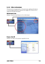
Page 107: ...ght corner of the screen give additional information on the motherboard and the contents of the support CD Click an icon to display the specified information Motherboard Info Motherboard Info Motherboard Info Motherboard Info Motherboard Info Displays the general specifications of the motherboard Browse this CD Browse this CD Browse this CD Browse this CD Browse this CD Displays the support CD con...

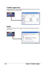
Page 108: ... Technical support Form Technical support Form Technical support Form Technical support Form Technical support Form Displays the ASUS Technical Support Request Form that you have to fill out when requesting technical support Filelist Filelist Filelist Filelist Filelist Displays the contents of the support CD and a brief description of each in text format ...

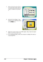
Page 109: ... to replace system boot Launch MyLogo to replace system boot Launch MyLogo to replace system boot Launch MyLogo to replace system boot Launch MyLogo to replace system boot logo before flashing BIOS logo before flashing BIOS logo before flashing BIOS logo before flashing BIOS logo before flashing BIOS then click Next Next Next Next Next 4 Select Update BIOS from a file Update BIOS from a file Updat...

Page 110: ...urns to the ASUS Update utility flash the original BIOS to load the new boot logo 10 After flashing the BIOS restart the computer to display the new boot logo during POST 8 Adjust the boot image to your desired size by selecting a value on the Ratio Ratio Ratio Ratio Ratio box 7 When the logo images appear on the right window pane select an image to enlarge by clicking on it ...

Page 111: ...m the BIOS screen select Advanced Advanced Advanced Advanced Advanced then Instant Music Instant Music Instant Music Instant Music Instant Music Configuration Configuration Configuration Configuration Configuration 4 In the Instant Music Configuration Instant Music Configuration Instant Music Configuration Instant Music Configuration Instant Music Configuration menu select the item Instant Music I...

Page 112: ...tion keys Set 2 Instant Music function keys Set 2 Instant Music function keys Set 2 Instant Music function keys Set 2 Instant Music function keys Set 2 CD ON OFF PLAY PAUSE STOP EJECT PREVIOUS NEXT VOL DOWN VOL UP SCROLL LOCK LED CAPS LOCK LED 3 Connect speakers or a headphone to the Line Out lime colored port on the rear panel for audio output You may also connect a headphone to the headphone jac...

Page 113: ...the Virtual Cable Tester To use the the Marvell Virtual Cable Tester utility 1 Launch the VCT utility from the Windows desktop by clicking Start All Programs Marvell Virtual Cable Tester Start All Programs Marvell Virtual Cable Tester Start All Programs Marvell Virtual Cable Tester Start All Programs Marvell Virtual Cable Tester Start All Programs Marvell Virtual Cable Tester 2 Click Virtual Cable...

Page 114: ...to activate the 6 channel audio feature You must use 4 channel or 6 channel speakers for this setup SoundMAX Digital Audio requires Windows 98SE ME 2000 XP operating system Make sure that one of these operating systems is installed before installing the SoundMAX Digital Audio software If the SoundMAX Digital Audio System is correctly installed you will find the SoundMAX Control Panel icon on the t...

Page 115: ... Audio upgrade Creative Digital Audio upgrade Creative Digital Audio upgrade Creative Digital Audio upgrade Creative Digital Audio upgrade The SoundBlaster Live Motherboard upgrade allows you to enhance your motherboard audio and use advanced tools to experience extraordinary and thrilling audio features This affordable upgrade includes state of the art audio such as voice enabled applications hom...

Page 116: ...r The SoundMAX Digital Audio System supports several audio technologies including SoundMAX SPX DLS by XG and General MIDI Microphone Microphone Microphone Microphone Microphone Follow the screen instructions to configure the microphone to your desired settings The functions of the Line Out lime Line In blue and Mic pink ports on the rear panel change when you select the 4 channel or 6 channel audi...

Reviews: