


4-12
Chapter 4: Motherboard Information
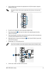
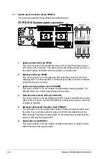
5.
Chassis Intrusion (2-pin INTRUSION1)
These leads are for the intrusion detection feature for chassis with intrusion sensor or
microswitch. When you remove any chassis component, the sensor triggers and sends
a high level signal to these leads to record a chassis intrusion event. The default setting
is to short the CHASSIS# and the GND pin by a jumper cap to disable the function.
4.
Fan Wafer connector (10-pin FAN_WAFER1)
This connector connects to the backplane and or FPB depending on the model, and
allows you to control the fan speed and control signals.
Summary of Contents for ESC4000 G4
Page 1: ...2U Rackmount Server ESC4000 G4 Series User Guide ...
Page 12: ...xii ...
Page 68: ...Chapter 2 Hardware Setup 2 40 ...
Page 74: ...4 2 Chapter 4 Motherboard Information 4 1 Z11PG D16 Motherboard layout ...
Page 154: ...6 18 Chapter 6 RAID Configuration ...
Page 172: ...7 18 Chapter 7 Driver Installation ...
Page 174: ...A 2 Appendix Z11PG D16 block diagram ...
Page 178: ...A 6 Appendix ...


