Asus Blitz Formula User Manual Download Page 90

4-16

Chapter 4: BIOS setup
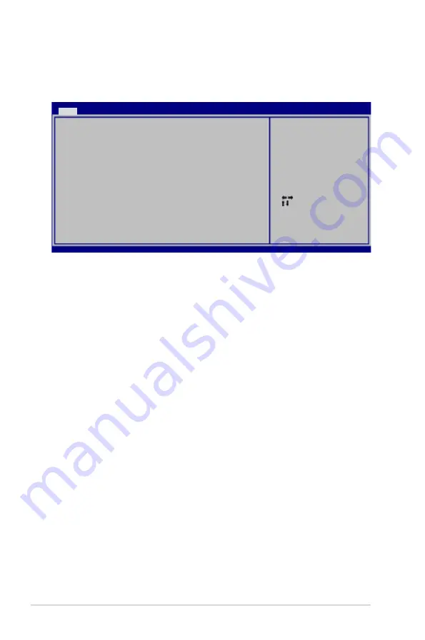
4.3.8 

System Information

This menu gives you an overview of the general system specifications. The BIOS 

automatically detects the items in this menu.

AMI BIOS

Displays the auto-detected BIOS information.

Processor

Displays the auto-detected CPU specification.

System Memory

Displays the auto-detected system memory.


Select Screen

    Select Item

F1   General Help

F10   Save and Exit

ESC   Exit

v02.58 (C)Copyright 1985-2007, American Megatrends, Inc.

BIOS SETUP UTILITY

Main 

AMIBIOS

Version    : 0145

Build Date : 05/04/07

Processor

Type       : Genuine Intel(R) CPU @ 2.40GHz

Speed      : 2400MHz

Count      : 1

System Memory

Available     : 512 MB

Summary of Contents for Blitz Formula

Page 1: ...Motherboard Blitz Formula ...

Page 2: ...RCHANTABILITY OR FITNESS FOR A PARTICULAR PURPOSE IN NO EVENT SHALL ASUS ITS DIRECTORS OFFICERS EMPLOYEES OR AGENTS BE LIABLE FOR ANY INDIRECT SPECIAL INCIDENTAL OR CONSEQUENTIAL DAMAGES INCLUDING DAMAGES FOR LOSS OF PROFITS LOSS OF BUSINESS LOSS OF USE OR DATA INTERRUPTION OF BUSINESS AND THE LIKE EVEN IF ASUS HAS BEEN ADVISED OF THE POSSIBILITY OF SUCH DAMAGES ARISING FROM ANY DEFECT OR ERROR IN...

Page 3: ...rview 2 5 2 2 1 Placement direction 2 5 2 2 2 Screw holes 2 5 2 2 3 Motherboard layout 2 6 2 2 4 Audio card layout 2 6 2 2 5 Layout contents 2 7 2 3 Central Processing Unit CPU 2 9 2 3 1 Installing the CPU 2 10 2 3 2 Installing the CPU heatsink and fan 2 12 2 3 3 Uninstalling the CPU heatsink and fan 2 14 2 3 4 Installing the optional fans 2 16 2 4 System memory 2 18 2 4 1 Overview 2 18 2 4 2 Memo...

Page 4: ...arting up for the first time 3 1 3 2 Turning off the computer 3 2 3 2 1 Using the OS shut down function 3 2 3 2 2 Using the dual function power switch 3 2 Chapter 4 BIOS setup 4 1 Managing and updating your BIOS 4 1 4 1 1 ASUS Update utility 4 1 4 1 2 Creating a bootable floppy disk 4 4 4 1 3 ASUS EZ Flash 2 utility 4 5 4 1 4 AFUDOS utility 4 6 4 1 5 ASUS CrashFree BIOS 3 utility 4 8 4 2 BIOS setu...

Page 5: ...n 4 23 4 5 3 CPU Configuration 4 25 4 5 4 Chipset 4 26 4 5 5 OnBoard Devices Configuration 4 27 4 5 6 PCI PnP 4 28 4 6 Power menu 4 29 4 6 1 Suspend Mode 4 29 4 6 2 Repost Video on S3 Resume 4 29 4 6 3 ACPI Version 4 29 4 6 4 ACPI APIC Support 4 29 4 6 5 APM Configuration 4 30 4 6 6 Hardware Monitor 4 31 4 7 Boot menu 4 35 4 7 1 Boot Device Priority 4 35 4 7 2 Boot Settings Configuration 4 36 4 7 ...

Page 6: ...S AI N O S 5 25 5 3 7 ASUS AI Gear 2 5 26 5 3 8 ASUS AI Nap 5 27 5 3 9 ASUS AI Booster 5 28 5 3 10 ASUS Q Fan 2 5 29 5 4 RAID configurations 5 30 5 4 1 RAID definitions 5 30 5 4 2 Installing Serial ATA hard disks 5 31 5 4 3 Intel RAID configurations 5 31 5 5 Creating a RAID driver disk 5 39 5 5 1 Creating a RAID driver disk without entering the OS 5 39 5 5 2 Creating a RAID SATA driver disk in Win...

Page 7: ...ause harmful interference to radio or television reception which can be determined by turning the equipment off and on the user is encouraged to try to correct the interference by one or more of the following measures Reorient or relocate the receiving antenna Increase the separation between the equipment and receiver Connect the equipment to an outlet on a circuit different from that to which the...

Page 8: ...cal power company If the power supply is broken do not try to fix it by yourself Contact a qualified service technician or your retailer Operation safety Before installing the motherboard and adding devices on it carefully read all the manuals that came with the package Before using the product make sure all cables are correctly connected and the power cables are not damaged If you detect any dama...

Page 9: ...o change system settings through the BIOS Setup menus Detailed descriptions of the BIOS parameters are also provided Chapter 5 Software support This chapter describes the contents of the support DVD that comes with the motherboard package and the software Appendix CPU features The Appendix describes the CPU features and technologies that the motherboard supports as well as the debug code table for...

Page 10: ...y3 If you must press two or more keys simultaneously the key names are linked with a plus sign Example Ctrl Alt D Command Means that you must type the command exactly as shown then supply the required item or value enclosed in brackets Example At the DOS prompt type the command line afudos i filename afudos iBlitz Formula ROM DANGER WARNING Information to prevent injury to yourself when trying to ...

Page 11: ...er to www asus com or this user manual for the Memory QVL Qualified Vendors Lists Expansion Slots 2 x PCIe x16 slots support dual graphics solution 3 x PCIe x1 PCIEx1_1 is compatible with the audio slot 2 x PCI 2 2 slots CrossFire Technology Supports AMD CrossFire graphics cards both at x8 mode Storage Southbridge 6 x SATA 3 0 Gb s ports Intel Matrix Storage Technology supports RAID 0 1 5 10 and J...

Page 12: ... purple 1 x S PDIF Out Coaxial Optical 1 x IEEE1394a port 2 x LAN RJ45 ports 6 x USB 2 0 1 1 ports 1 x Clr CMOS switch Internal I O Connectors 3 x USB connectors support additional 6 USB ports 1 x Floppy disk drive connector 1 x IDE connector for two devices 6 x SATA connectors 8 x Fan connectors 1 x CPU 1 x Power 4 x Chassis 2 x Optional 2 x Thermal sensor connectors 1 x IEEE1394a connector 1 x S...

Page 13: ...rial ATA power cables 2 port USB2 0 IEEE 1394a module I O Shield Cable ties User s manual Software The hottest 3D game S T A L K E R Blitz Formula Support DVD Drivers ASUS PC Probe II ASUS Update ASUS AI Suite Futuremark 3DMark 06 Advanced Edition Kaspersky Anti virus software Form Factor ATX Form Factor 12 x 9 6 30 5 cm x 24 4 cm Specifications are subject to change without notice ...

Page 14: ...xiv ...

Page 15: ...1 Product introduction This chapter describes the motherboard features and the new technologies it supports ...

Page 16: ...ROG Blitz Formula Chapter summary 1 1 1 Welcome 1 1 1 2 Package contents 1 1 1 3 Special features 1 2 ...

Page 17: ...low If any of the above items is damaged or missing contact your retailer 1 2 Package contents Check your motherboard package for the following items Motherboard ROG Blitz Formula I O module USB 2 0 IEEE 1394a module Cables Ultra DMA 133 100 66 cable Floppy disk drive cable Serial ATA cables Serial ATA power cables Accessories I O shield ASUS Optional Fan Fusion Block System Accessory LCD Poster D...

Page 18: ...r is one of the most powerful CPU in the world See page 2 9 for details Intel Core 2 Duo Intel Core 2 Extreme CPU support This motherboard supports the latest Intel Core 2 processor in the LGA775 package and Intel s next generation 45nm multi core processors With the new Intel Core microarchitecture technology and 1333 1066 800 MHz FSB the Intel Core 2 is one of the most powerful and energy effici...

Page 19: ...ides even more precise overclocking options to unleash the true potential of DDR2 memory The DDR2 Mode maximizes system performance by eliminating the bottleneck when overclocking both the CPU and memory providing great performance for 3D graphics and other memory demanding applications See page 2 19 for details Serial ATA 3 0 Gb s technology This motherboard supports the next generation hard driv...

Page 20: ...stem Building on the ROG unique heatpipe the Fusion Block System FBS provides dual paths to cool down the motherboard Users will be able to connect the FBS with the watercooling circuit Component Overheat Protection EX COP EX When the temperature of Northbridge and Southbridge reaches the limit of specifications the motherboard will automatically shut down to protect NB and SB from burning 2 Phase...

Page 21: ...ilities and benchmark scores See page 4 20 for details Extreme Tweaker This feature allows you to fine tune the various voltage settings and gradually increase the memory Front Side Bus FSB and PCI Express frequency at 1MHz increment to achieve maximum system performance See page 4 17 for details AI NOS Non Delay Overclocking System The patented ASUS Non delay Overclocking System AI NOS technology...

Page 22: ...mputer fans air conditioners and other background noises then eliminates it in the incoming audio stream while recording LCD Poster The LCD Poster displays actual boot error messages instead of codes that other debug cards show This unique feature allows you to easily find out which devices fail during the boot process eliminating guesswork and allowing you to solve the problem immediately See pag...

Page 23: ...solution makes system more stable and enhances the overclocking capability AI Gear 2 AI Gear 2 allows you to choose profiles to adjust the CPU frequency and Vcore voltage to minimize system noise and power consumption You can change the mode in real time in the operating system to max power saving mode and save up to 50 power when using word processing applications See page 5 26 for details AI Nap...

Page 24: ...ed circuit board PCB to dissipate heat these critical components generate ASUS EZ DIY ASUS EZ DIY feature collection provides you easy ways to install computer components update the BIOS or back up your favorite settings ASUS Q Connector The ASUS Q Connector allows you to connect or disconnect chassis front panel cables in one easy step This unique adapter eliminates the trouble of plugging in one...

Page 25: ... Hardware information This chapter lists the hardware setup procedures that you have to perform when installing system components It includes description of the jumpers and connectors on the motherboard ...

Page 26: ...2 2 1 Before you proceed 2 1 2 2 Motherboard overview 2 5 2 3 Central Processing Unit CPU 2 9 2 4 System memory 2 18 2 5 Expansion slots 2 24 2 6 Jumper 2 27 2 7 Aduio card I O shield and LCD Poster Installation 2 28 2 8 Connectors 2 30 ...

Page 27: ...ve any component ensurethat the ATX power supply is switched off or the power cord is detached from the power supply Failure to do so may cause severe damage to the motherboard peripherals and or components BLITZ FORMULA BLITZ FORMULA CPU LED CPU_CRAZY CPU_HIGH CPU_NORMAL Onboard LEDs The motherboard comes with LEDs that indicate the voltage conditions of CPU memory northbridge southbridge and FSB...

Page 28: ...bridge LED displays either the North Bridge Voltage or the FSB Termination Voltage The southbridge LED shows either the PLL Voltage or the South Bridge Voltage You can select the voltage to display in BIOS Refer to the illustration below for the location of the northbridge southbridge LEDs and the table below for LED definition Normal green High yellow Crazy red DRAM Voltage 1 80 2 20 2 22 2 60 2 ...

Page 29: ...333 399 Default 400 499 Overclocking 500 549 Overclocking 550 599 Overclocking 600 Overclocking 1 Default 2 3 4 5 Fast BLITZ FORMULA BLITZ FORMULA Frequency LED Fast Default 4 FSB frenquency LED There are five LEDs that light up to indicate the level of FSB frequency One lit blue LED suggests that the frequency is low default while five lit blue LEDs shows that the frequency is high fast Refer to ...

Page 30: ...rd disk drive connected to the motherboard or when the hard disk drive does not function BLITZ FORMULA BLITZ FORMULA Power on switch 6 Power LED The motherboard comes with a power on switch that lights up to indicate that the system is ON in sleep mode or in soft off mode This is a reminder that you should shut down the system and unplug the power cable before removing or plugging in any motherboa...

Page 31: ...l injury and damage motherboard components DO NOT overtighten the screws Doing so can damage the motherboard 2 2 1 Placement direction When installing the motherboard make sure that you place it into the chassis in the correct orientation The edge with external ports goes to the rear part of the chassis as indicated in the image below 2 2 2 Screw holes Place nine 9 screws into the holes indicated ...

Page 32: ...odule DDR2 DIMM_B1 64 bit 240 pin module DDR2 DIMM_B2 64 bit 240 pin module CHA_FAN2 BIOS PCIEX1_1 PCIEX1_2 PCIEX1_3 PCI1 PCIEX16_1 PCIEX16_2 PCI2 SATA56 SATA34 SATA12 IDT PES24N3A LAN1_USB12 VIA VT6308P OPT_TEMP1 CHA_FAN4 ADH DDR_CRAZY DDR_HIGH DDR_NORMAL USB910 OPT_FAN2 OPT_TEMP2 CLR_CMOS CPU_CRAZY CPU_HIGH CPU_NORMAL PWR_SW RST_SW PRI_EIDE SPDIF_O12 E1394 LCD_CON SB_CRAZY SB_HIGH SB_NORMAL FREQ...

Page 33: ...board port purple 2 30 2 Coaxial S PDIF Out port 2 30 3 LAN 2 RJ 45 port 2 30 4 LAN 1 RJ 45 port 2 30 5 Line In port light blue 2 31 6 Line Out port lime 2 31 7 Microphone port pink 2 31 8 Center Subwoofer port orange 2 31 9 Rear Speaker Out port black 2 31 10 Side Speaker Out port gray 2 31 11 USB 2 0 ports 1 2 3 and 4 2 31 12 IEEE 1394a port 2 31 13 Clear CMOS switch 2 31 14 Optical S PDIF Out p...

Page 34: ...0 1 pin IE1394_2 2 35 6 Thermal sensor cable connectors 2 pin OPT_TEMP1 2 2 35 7 CPU chassis and optional fan connectors 4 pin CPU_FAN 3 pin CHA_FAN1 4 3 pin PWR_FAN 3 pin OPT_FAN1 2 2 36 8 Chassis intrusion connector 4 1 pin CHASSIS 2 37 9 ATX power connectors 24 pin EATXPWR 8 pin EATX12V 2 37 10 Digital audio connector 4 1 pin SPDIF_OUT for ASUS HDMI VGA card 2 38 11 System panel connector 20 8 ...

Page 35: ...t contacts motherboard components ASUS will shoulder the cost of repair only if the damage is shipment transit related Keep the cap after installing the motherboard ASUS will process Return Merchandise Authorization RMA requests only if the motherboard comes with the cap on the LGA775 socket The product warranty does not cover damage to the socket contacts resulting from incorrect CPU installation...

Page 36: ...b Retention tab Load lever This side of the socket box should face you PnP cap A B To prevent damage to the socket pins do not remove the PnP cap unless you are installing a CPU 2 3 1 Installing the CPU To install a CPU 1 Locate the CPU socket on the motherboard Before installing the CPU make sure that the cam box is facing towards you and the load lever is on your left BLITZ FORMULA BLITZ FORMULA...

Page 37: ...N1 connector to ensure system stability A B The CPU fits in only one correct orientation DO NOT force the CPU into the socket to prevent bending the connectors on the socket and damaging the CPU The motherboard supports Intel LGA775 processors with the Intel Enhanced Memory 64 Technology EM64T Enhanced Intel SpeedStep Technology EIST and Hyper Threading Technology Refer to the Appendix for more in...

Page 38: ...e only Intel certified multi directional heatsink and fan Your Intel LGA775 heatsink and fan assembly comes in a push pin design and requires no tool to install If you purchased a separate CPU heatsink and fan assembly make sure that you have properly applied Thermal Interface Material to the CPU heatsink or CPU before you install the heatsink and fan assembly Make sure that you have installed the...

Page 39: ... fasteners at a time in a diagonal sequence to secure the heatsink and fan assembly in place B A A A B B DO NOT forget to connect the CPU fan connector Hardware monitoring errors can occur if you fail to plug this connector BLITZ FORMULA GND CPU FAN PWR CPU FAN IN CPU FAN PWM BLITZ FORMULA CPU fan connector CPU_FAN A B ...

Page 40: ... a diagonal sequence to disengage the heatsink and fan assembly from the motherboard B B A A A A B B 4 Carefully remove the heatsink and fan assembly from the motherboard To uninstall the CPU heatsink and fan 1 Disconnect the CPU fan cable from the connector on the motherboard 2 Rotate each fastener counterclockwise ...

Page 41: ...tation when reinstalling Narrow end of the groove Refer to the documentation in the boxed or stand alone CPU fan package for detailed information on CPU fan installation The narrow end of the groove should point outward after resetting The photo shows the groove shaded for emphasis ...

Page 42: ...nal fan with an active CPU cooler will interfere with the airflow and destabilize the system 1 Position the fan above the pipe and heatsink assembly 2 Fit the fan to the grooved edge of the heatsink 3 Carefully push down the fan until it snugly fits the heatsink then connect the fan cable 4 The photo shows the fan installed on the motherboard Optional fan on one side fins ...

Page 43: ...eatsink then connect the fan cable 4 The photo shows the fans installed on the motherboard When you are using water cooling modules make sure to install TWO optional fans to obtain more effective heat dissipation Optional fan on the other side fins Plug the optional fan cables to any of the CHA_FAN1 CHA_FAN4 and PWR_FAN connectors on the motherboard Make sure the optional fan is installed correctl...

Page 44: ...R2 DIMM sockets BLITZ FORMULA BLITZ FORMULA 240 pin DDR2 DIMM sockets DIMM_A2 DIMM_A1 DIMM_B2 DIMM_B1 If you install a DDR2 1066 memory module make sure that you set the DRAM Frequency item in BIOS to DDR2 1066MHz See section 4 4 Extreme Tweaker menu for details FSB DDR2 1333 1066 1333 800 1333 667 1066 1066 1066 800 1066 667 This chipset officially supports DDR2 800 MHz With the ASUS Super Memspe...

Page 45: ...hysical Address Extension PAE If you install Windows XP Vista 32 bit operation system a total memory of less than 3GB is recommended This motherboard does not support memory modules made up of 128 Mb chips Mode Sockets DIMM_A1 DIMM_A2 DIMM_B1 DIMM_B2 Single Channel Populated Populated Dual channel 1 Populated Populated Dual channel 2 Populated Populated Populated Populated 64 bit Windows XP Profes...

Page 46: ...n any slot as Single channel memory configuration B Supports one pair of modules inserted into either the blue slots or the white slots as one pair of Dual channel memory configuration C Supports 4 modules inserted into both the blue and white slots as two pairs of Dual channel memory configuration Visit the ASUS website for the latest DDR2 1000 800 667MHz QVL Size Vendor Chip No SS DS Part No DIM...

Page 47: ...KI5 1024MB KINGMAX KKA8FEIBF HJK 25A DS KLDD48F ABKI5 512MB Transcend HY5PS12821CFP S5 SS TS64MLQ64V8J 1024MB Transcend HY5PS12821CFP S5 DS TS128MLQ64V8J 512MB Super Talent Heat Sink Package SS T800UA12C4 1024MB Super Talent Heat Sink Package DS T800UB1GC4 512MB NANYA NT5TU64M8BE 25C SS NT512T64U880BY 25C 1024MB NANYA NT5TU64M8BE 25C DS NT1GT64U8HB0BY 25C 512MB PSC A3R12E3HEF641B9A05 SS AL6E8E63B8...

Page 48: ... DATA AD29608A8A 3EG DS M2OAD5G3I4176I1C52 2048MB A DATA NT5TU128M8BJ 3C DS M2ONY5H3J4170I1C5Z 512MB crucial Heat Sink Package SS BL6464AA663 8FD 1024MB crucial Heat Sink Package DS BL12864AA663 16FD 1024MB crucial Heat Sink Package DS BL12864AL664 16FD 1024MB crucial Heat Sink Package DS BL12864AA663 16FD2 512MB Apacer AM4B5708GQJS7E0628F SS AU512E667C5KBGC 1024MB Apacer AM4B5708GQJS7E DS AU01GE6...

Page 49: ...aining clips snap back in place and the DIMM is properly seated 2 4 4 Removing a DIMM To remove a DIMM 1 Simultaneously press the retaining clips outward to unlock the DIMM 2 Remove the DIMM from the socket Support the DIMM lightly with your fingers when pressing the retaining clips The DIMM might get damaged when it flips out with extra force Unlocked retaining clip DDR2 DIMM notch 1 2 3 1 A DDR2...

Page 50: ...Secure the card to the chassis with the screw you removed earlier 6 Replace the system cover 2 5 2 Configuring an expansion card After installing the expansion card configure it by adjusting the software settings 1 Turn on the system and change the necessary BIOS settings if any See Chapter 4 for information on BIOS setup 2 Assign an IRQ to the card Refer to the tables on the next page 3 Install t...

Page 51: ...controller 1 shared USB 2 0 controller 2 shared SATA controller 1 shared SATA controller 2 shared IRQ Priority Standard function 0 1 System timer 1 2 Keyboard controller 2 Re direct to IRQ 9 3 11 IRQ holder for PCI steering 4 12 Communications port COM1 5 13 IRQ holder for PCI steering 6 14 Floppy disk controller 7 15 Printer port LPT1 8 3 System CMOS Real Time Clock 9 4 IRQ holder for PCI steerin...

Page 52: ...x1 slot prior to a PCIE x16 slot 2 5 6 PCI Express x16 slots This motherboard supports two ATI CrossFire PCI Express x16 graphics cards that comply with the PCI Express specifications Refer to the figure below for the location of the slots In CrossFire mode install the ATI CrossFire Edition Master graphics card on the primary PCI Express slot Install two ATI graphics cards from the same GPU family...

Page 53: ... Enable CLR_CMOS Default clr CMOS switch behavior System power state G3 S5 S0 DOS mode S0 OS mode S1 S3 S4 Clearing CMOS G3 Power off without 5VSB power AC power loss S5 Power off with 5VSB power The system shuts dowm immediately The clr CMOS switch will not function if the jumper cap on CLRTC_SW is moved to the Disable position but the shutdwon function in S0 mode DOS mode still works Make sure t...

Page 54: ...ion 2 7 1 Audio card Installation 1 Take out the Audio card from the package 2 Locate the audio slot on the motherboard 3 Align the card connector with the slot and press firmly until the card sits on the slot completely 4 The photo below shows the audio card installed on the motherboard ...

Page 55: ...to the onboard connector labeled LCD_CON 5 This photo shows the LCD Poster installed Place the device wherever you can monitor the screen 1 Install the I O shield to the chassis rear panel Orient the I O shield so that the openings of the ports fit the motherboard rear ports Snaps the I O shield into place 2 7 2 I O shield and LCD Poster Installation Be cautious when installing the I O shield The ...

Page 56: ...port This port allows Gigabit connection to a Local Area Network LAN through a network hub Refer to the table below for the LAN port LED indications 2 1 14 15 3 4 5 11 12 13 clr CMOS Line in Mic in Cen Sub Rear out Side out Front out 6 7 8 9 10 32 bit OS LAN port LED indications Blinking Activity Link Speed LED Description OFF OFF Soft off Mode YELLOW OFF During Power ON OFF YELLOW ORANGE 100 Mbps...

Page 57: ...iguration Audio 2 4 6 or 8 channel configuration Port Headset 2 channel 4 channel 6 channel 8 channel Light Blue Line In Line In Line In Line In Lime Line Out Front Speaker Out Front Speaker Out Front Speaker Out Pink Mic In Mic In Mic In Mic In Orange Center Subwoofer Center Subwoofer Black Rear Speaker Out Rear Speaker Ou Rear Speaker Out Gray Side Speaker Out 11 USB 2 0 ports 1 2 3 and 4 These ...

Page 58: ...le blue black and gray Connect the blue connector to the motherboard s IDE connector then select one of the following modes to configure your device Pin 20 on the IDE connector is removed to match the covered hole on the Ultra DMA cable connector This prevents incorrect insertion when you connect the IDE cable Use the 80 conductor IDE cable for Ultra DMA 133 100 66 IDE devices If any device jumper...

Page 59: ...TXP2 RSATA_TXN2 GND RSATA_RXP2 RSATA_RXN2 GND SATA2 GND RSATA_TXP4 RSATA_TXN4 GND RSATA_RXP4 RSATA_RXN4 GND SATA4 GND RSATA_TXP5 RSATA_TXN5 GND RSATA_RXP5 RSATA_RXN5 GND SATA5 GND RSATA_TXP6 RSATA_TXN6 GND RSATA_RXP6 RSATA_RXN6 GND SATA6 These connectors are set to Standard IDE mode by default In Standard IDE mode you can connect Serial ATA boot data hard disk drives to these connectors If you int...

Page 60: ... connectors are for USB 2 0 ports Connect the USB module cable to any of these connectors then install the module to a slot opening at the back of the system chassis These USB connectors comply with USB 2 0 specification that supports up to 480 Mbps connection speed BLITZ FORMULA BLITZ FORMULA USB 2 0 connectors USB 5V USB_P12 USB_P12 GND NC USB 5V USB_P11 USB_P11 GND USB1112 USB 5V USB_P10 USB_P1...

Page 61: ...stall the Q Connector 1394 to the 1394 connector onboard 6 Thermal sensor cable connectors 2 pin OPT_TEMP1 2 These connectors are for temperature monitoring Connect the thermal sensor cables to these connectors and place the other ends to the devices which you want to monitor temperature The optional fan1 2 can work with the temperature sensors for a better cooling effect BLITZ FORMULA BLITZ FORMU...

Page 62: ...em may damage the motherboard components These are not jumpers DO NOT place jumper caps on the fan connectors BLITZ FORMULA BLITZ FORMULA Fan connectors CPU_FAN GND CPU FAN PWR CPU FAN IN CPU FAN PWM PWR_FAN GND Rotation 12V OPT_FAN1 OPT_FAN2 GND Rotation 12V CHA_FAN2 GND Rotation 12V CHA_FAN4 GND Rotation 12V CPU_FAN PWR_FAN CHA_FAN4 CHA_FAN1 CHA_FAN3 OPT_FAN1 OPT_FAN2 CHA_FAN2 GND Rotation 12V C...

Page 63: ...removed or replaced The signal is then generated as a chassis intrusion event By default the pin labeled Chassis Signal and Ground are shorted with a jumper cap Remove the jumper caps only when you intend to use the chassis intrusion detection feature BLITZ FORMULA BLITZ FORMULA Chassis intrusion connector CHASSIS 5VSB_MB Chassis Signal GND Default BLITZ FORMULA BLITZ FORMULA ATX power connectors ...

Page 64: ...later version and provides a minimum power of 400 W Do not forget to connect the 4 pin 8pin EATX12V power plug otherwise the system will not boot Use of a PSU with a higher power output is recommended when configuring a system with more power consuming devices The system may become unstable or may not boot up if the power is inadequate The ATX 12 V Specification 2 0 compliant 400W PSU has been tes...

Page 65: ...e speaker allows you to hear system beeps and warnings ATX power button soft off button 2 pin PWRSW This connector is for the system power button Pressing the power button turns the system on or puts the system in sleep or soft off mode depending on the BIOS settings Pressing the power switch for more than four seconds while the system is ON turns the system OFF Reset button 2 pin RESET This 2 pin...

Page 66: ...Connect the front panel cables to the ASUS Q Connector Refer to the labels on the Q Connector to know the detailed pin definitions then match them to the respective front panel cable labels 2 Install the ASUS Q Connector to the system panel connector making sure the orientation matches the labels on the motherboard 3 The front panel functions are now enabled The figure shows the Q Connector proper...

Page 67: ...case system This is ideal for overclockers and gamers who continually change settings to enhance system performance 1 Power on switch Press the power on switch to wake power up the system BLITZ FORMULA BLITZ FORMULA Power on switch 2 Reset switch Press the reset switch to reboot the system BLITZ FORMULA BLITZ FORMULA Reset switch ...

Page 68: ... 2 Arrange and stick the rubber studs to wherever you wish to place your motherboard 3 Put the motherboard on the DIY Pedestal to get more efficient heat dissipation The tape on the rubber studs is for one time use Replace the tape if the adhesive surface does not work You can use the DIY Pedestal in ways that suit your needs ...

Page 69: ...3 Powering up This chapter describes the power up sequence the vocal POST messages and ways of shutting down the system ...

Page 70: ...ROG Blitz Formula Chapter summary 3 3 1 Starting up for the first time 3 1 3 2 Turning off the computer 3 2 ...

Page 71: ...ndby feature the monitor LED may light up or switch between orange and green after the system LED turns on The system then runs the power on self tests or POST While the tests are running the BIOS beeps see BIOS beep codes table below or additional messages appear on the screen If you do not see anything within 30 seconds from the time you turned on the power the system may have failed a power on ...

Page 72: ...ing Windows Vista 1 Click the Start button then select ShutDown 2 The power supply should turn off after Windows shuts down 3 2 2 Using the dual function power switch While the system is ON pressing the power switch for less than four seconds puts the system to sleep mode or to soft off mode depending on the BIOS setting Pressing the power switch for more than four seconds lets the system enter th...

Page 73: ...4 BIOS setup This chapter tells how to change the system settings through the BIOS Setup menus Detailed descriptions of the BIOS parameters are also provided ...

Page 74: ...tz Formula 4 1 Managing and updating your BIOS 4 1 4 2 BIOS setup program 4 9 4 3 Main menu 4 12 4 4 Extreme Tweaker menu 4 17 4 5 Advanced menu 4 22 4 6 Power menu 4 29 4 7 Boot menu 4 35 4 8 Tools menu 4 39 4 9 Exit menu 4 41 ...

Page 75: ... the BIOS in the future Copy the original motherboard BIOS using the ASUS Update or AFUDOS utilities Installing ASUS Update To install ASUS Update 1 Place the support DVD in the optical drive The Drivers menu appears 2 Click the Utilities tab then click Install ASUS Update VX XX XX 3 The ASUS Update utility is copied to your system 4 1 1 ASUS Update utility The ASUS Update is a utility that allows...

Page 76: ...k traffic or click Auto Select Click Next Updating the BIOS through the Internet To update the BIOS through the Internet 1 Launch the ASUS Update utility from the Windows desktop by clicking Start Programs ASUS ASUSUpdate ASUSUpdate The ASUS Update main window appears 2 Select Update BIOS from the Internet option from the drop down menu then click Next ...

Page 77: ...le option from the drop down menu then click Next 4 From the FTP site select the BIOS version that you wish to download Click Next 5 Follow the screen instructions to complete the update process The ASUS Update utility is capable of updating itself through the Internet Always update the utility to avail all its features 3 Locate the BIOS file from the Open window then click Open 4 Follow the scree...

Page 78: ...er Windows XP environment a Insert a 1 44 MB floppy disk to the floppy disk drive b Click Start from the Windows desktop then select My Computer c Select the 3 1 2 Floppy Drive icon d Click File from the menu then select Format A Format 3 1 2 Floppy Disk window appears e Select Create an MS DOS startup disk from the format options field then click Start 2 Copy the original or the latest motherboar...

Page 79: ...ves by pressing Tab before the correct file is found Then press Enter 3 You can launch the EZ Flash 2 by two methods 1 Insert the floppy disk USB flash disk that contains the BIOS file to the floppy disk drive or the USB port Press Alt F2 during POST to display the following This function can support devices such as USB flash disk or floppy disk with FAT 32 16 format and single partition only DO N...

Page 80: ... eight alphanumeric characters for the main filename and three alphanumeric characters for the extension name A afudos oOLDBIOS1 rom Make sure that the floppy disk is not write protected and has at least 1024KB free space to save the file The succeeding BIOS screens are for reference only The actual BIOS screen displays may not be same as shown The utility returns to the DOS prompt after copying t...

Page 81: ...mula ROM AMI Firmware Update Utility Version 1 19 ASUS V2 07 03 11 24BB Copyright C 2002 American Megatrends Inc All rights reserved WARNING Do not turn off power during flash BIOS Reading file done Reading flash done Advance Check Erasing flash done Writing flash done Verifying flash done Please restart your computer A A afudos iBlitz Formula ROM AMI Firmware Update Utility Version 1 19 ASUS V2 0...

Page 82: ... after the utility completes the updating process Only the USB flash disk with FAT 32 16 format and single partition can support ASUS CrashFree BIOS 3 The device size should be smaller than 8GB DO NOT shut down or reset the system while updating the BIOS Doing so can cause system boot failure When found the utility reads the BIOS file and starts flashing the corrupted BIOS file Recovering the BIOS...

Page 83: ...program Press Del during the Power On Self Test POST to enter the Setup utility otherwise POST continues with its test routines If you wish to enter Setup after POST restart the system by pressing Ctrl Alt Delete or by pressing the reset button on the system chassis You can also restart by turning the system off and then back on Do this last option only if the first two failed The Setup program is...

Page 84: ...of a menu screen are the navigation keys for that particular menu Use the navigation keys to select items in the menu and change the settings 4 2 1 BIOS menu screen Some of the navigation keys differ from one screen to another Select Screen Select Item Change Field Tab Select Field F1 General Help F10 Save and Exit ESC Exit v02 58 C Copyright 1985 2007 American Megatrends Inc BIOS SETUP UTILITY Ma...

Page 85: ...change the value of a field select it then press Enter to display a list of options Refer to 4 2 7 Pop up window 4 2 7 Pop up window Select a menu item then press Enter to display a pop up window with the configuration options for that item 4 2 8 Scroll bar A scroll bar appears on the right side of a menu screen when there are items that do not fit on the screen Press the Up Down arrow keys or Pag...

Page 86: ...ions Chinese BIG5 Chinese GB Japanese Français German English Refer to section 4 2 1 BIOS menu screen for information on the menu screen items and how to navigate through them Select Screen Select Item Change Field Tab Select Field F1 General Help F10 Save and Exit ESC Exit v02 58 C Copyright 1985 2007 American Megatrends Inc BIOS SETUP UTILITY Main Extreme Tweaker Advanced Power Boot Tools Exit S...

Page 87: ...RMD LBA Large Mode Auto Enables or disables the LBA mode Setting to Auto enables the LBA mode if the device supports this mode and if the device was not previously formatted with LBA mode disabled Configuration options Disabled Auto Block Multi sector Transfer Auto Enables or disables data multi sectors transfers When set to Auto the data transfer from and to the device occurs multiple sectors at ...

Page 88: ...torage driver to enable advanced Serial ATA features that increases storage performance on random workloads by allowing the drive to internally optimize the order of commands If you want to create a RAID 0 RAID 1 RAID 5 RAID 10 or the Intel Matrix Storage Technology configuration from the Serial ATA hard disk drives set this item to RAID If you want to use the Serial ATA hard disk drives as Parall...

Page 89: ...o configure AHCI settings It appears only when you set the Configure SATA as item to AHCI in the SATA Configuration menu AHCI Settings AHCI Port1 Not Detected AHCI Port2 Not Detected AHCI Port3 Not Detected AHCI Port4 Not Detected AHCI Port5 Not Detected AHCI Port6 Not Detected While entering setup BIOS auto detects the presence of SATA devices This displays the status of auto detection of SATA de...

Page 90: ... BIOS information Processor Displays the auto detected CPU specification System Memory Displays the auto detected system memory Select Screen Select Item F1 General Help F10 Save and Exit ESC Exit v02 58 C Copyright 1985 2007 American Megatrends Inc BIOS SETUP UTILITY Main AMIBIOS Version 0145 Build Date 05 04 07 Processor Type Genuine Intel R CPU 2 40GHz Speed 2400MHz Count 1 System Memory Availa...

Page 91: ... than CPU manufacturer recomends are not guaranteed to be stable If the system becomes unstable return to the default 4 4 1 Configure System Frequency Voltage AI Overclocking Auto Allows selection of CPU overclocking options to achieve desired CPU internal frequency Selct either one of the preset overclocking configuration options Manual Allows you to individually set overclocking parameters Auto ...

Page 92: ...clock 30 CPU Ratio Control Auto Configuration options Auto Manual The following item appears when the CPU Ratio Control item is set to Manual Ratio CMOS Setting 12 Use the and keys to select the CMOS ratio values from 6 to 12 FSB Frequency XXX Displays the frequency sent by the clock generator to the system bus and PCI bus Use the and keys to adjust the FSB frequency You can also type the desired ...

Page 93: ...o 1 DRAM Clocks 15 DRAM Clocks TRFC Auto Configuration options Auto 20 DRAM Clocks 25 DRAM Clocks 30 DRAM Clocks 35 DRAM Clocks 42 DRAM Clocks TWTR Auto Configuration options Auto 1 DRAM Clocks 15 DRAM Clocks TRRD Auto Configuration options Auto 1 DRAM Clocks 15 DRAM Clocks TRTP Auto Configuration options Auto 1 DRAM Clocks 15 DRAM Clocks DRAM Static Read Control Auto Configuration options Auto Di...

Page 94: ...ation options Auto 0 531V 0 545V 0 561V 0 576V 0 581V 0 597V 0 618V 0 635V Loadline Calibration Auto Configuration options Auto Disabled Enabled FSB Termination Voltage Auto Allows you to select the front side bus FSB termination voltage The text color in the configuration field indicates FSB termination voltage condition When you set the NB LED Selection item to FSBT Volt the onboard northbridge ...

Page 95: ... DDRII Controller REF Voltage Auto Allows you to manually set the memory voltage or you can set to Auto for the safe mode Configuration options DDRII_REF 30mv DDRII_REF 20mv DDRII_REF 10mv DDRII_REF DDRII_REF 10mv DDRII_REF 20mv DDRII_REF 30mv South Bridge Voltage Auto Allows you to select the southbridge voltage The text color in the configuration field indicates southbridge voltage condition Whe...

Page 96: ...voltage PLL Volt and southbridge voltage SB Volt Configuration options PLL Volt SB Volt 4 5 Advanced menu The Advanced menu items allow you to change the settings for the CPU and other system devices v02 58 C Copyright 1985 2007 American Megatrends Inc BIOS SETUP UTILITY Main Extreme Tweaker Advanced Power Boot Tools Exit AI Net 2 USB Configuration CPU Configuration Chipset Onboard Devices Configu...

Page 97: ...07 American Megatrends Inc USB Configuration USB Devices Enabled None USB Functions Enabled USB 2 0 Controller Enabled USB 2 0 Controller Mode HiSpeed BIOS EHCI Hand off Enabled Port 64 60 Emulation Disabled Legacy USB Support Auto Options Enabled Disabled BIOS SETUP UTILITY Advanced 4 5 1 AI Net 2 POST Check LAN Cable Disabled Enables or disables checking of the LAN cable during the Power On Self...

Page 98: ... Enabled Legacy USB Support Auto Allows you to enable or disable the support for legacy USB devices Setting to Auto allows the system to detect the presence of USB devices at startup If detected the USB controller legacy mode is enabled If no USB device is detected the legacy USB support is disabled Configuration options Disabled Enabled Auto USB 2 0 Controller Enabled Allows you to enable or disa...

Page 99: ...unctions Configuration options Disabled Enabled Vanderpool Technology Enabled Configuration options Enabled Disabled CPU TM function Enabled Configuration options Disabled Enabled Execute Disable Bit Enabled Allows you to enable or disable the No Execution Page Protection Technology Setting this item to Disabled forces the XD feature flag to always return to zero 0 Configuration options Disabled E...

Page 100: ...BIOS SETUP UTILITY Advanced North Bridge Chipset Configuration Memory Remap Feature Enabled Initiate Graphic Adapter PEG PCI PEG Port Control Auto North Bridge Chipset Configuration ENABLE Allow remapping of overlapped PCI memory above the total physical memory DISABLE Do not allow remapping of memory BIOS SETUP UTILITY Advanced Memory Remap Feature Enabled Allows you to enable or disable the rema...

Page 101: ...Bit LAN 1 Enabled Configuration options Enabled Disabled LAN Boot ROM Disabled Configuration options Disabled Enabled MarvelI GigaBit LAN 2 Enabled Configuration options Enabled Disabled LAN Boot ROM Disabled Configuration options Disabled Enabled VIA Firewire 1394 Enabled Configuration options Enabled Disabled Select Screen Select Item Change Option F1 General Help F10 Save and Exit ESC Exit v02 ...

Page 102: ...I PnP Settings WARNING Setting wrong values in below sections may cause system to malfunction Plug And Play O S No NO lets the BIOS configure all the devices in the system YES lets the operating system configure Plug and Play PnP devices not required for boot if your system has a Plug and Play operating system BIOS SETUP UTILITY Advanced Plug And Play O S No When set to No BIOS configures all the ...

Page 103: ...ation and Power Interface ACPI version supported Configuration options Disabled Enabled 4 6 4 ACPI APIC Support Enabled Allows you to enable or disable the Advanced Configuration and Power Interface ACPI support in the Advanced Programmable Interrupt Controller APIC When set to Enabled the ACPI APIC table pointer is included in the RSDT pointer list Configuration options Disabled Enabled Select Sc...

Page 104: ...e PME to wake up from S5 by PCI devices Configuration options Disabled Enabled Power On By PCIE Devices Disabled Allows you to enable or disable the PCIE devices to generate a wake event Configuration options Disabled Enabled Power On By PS 2 Keyboard Disabled Allows you to disable the Power On by PS 2 keyboard function or set specific keys on the PS 2 keyboard to turn on the system This feature r...

Page 105: ... item varies depending on whether you set the South Bridge Sensor Select item to SB Overheat Protection or OPT_TEMP2 v02 58 C Copyright 1985 2006 American Megatrends Inc Select Screen Select Item Change Field F1 General Help F10 Save and Exit ESC Exit Hardware Monitor CPU Temperature 38 5ºC 102ºF MB Temperature 36ºC 96 5ºF NB Temperature 35ºC 95ºF SB Temperature 43ºC 109ºF OPT Temperature N A Nort...

Page 106: ...Configuration options Disabled 50C 60C 70C 80C 90C CPU Fan and Chassis Fan Select Screen Select Item Change Field F1 General Help F10 Save and Exit ESC Exit CPU Fan Speed 4411RPM CPU Q Fan Control Disabled Chassis Fan 1 Speed N A Chassis Fan 2 Speed N A Chassis Fan 3 Speed N A Chassis Q Fan Control N A Chassis Fan 4 Speed N A CPU Fan Speed BIOS SETUP UTILITY Power v02 58 C Copyright 1985 2007 Amer...

Page 107: ... OPT_Fan 1 Speed N A OPT_Fan1 Q Fan Control DUTY CYCLE Duty Cycle Mode 90 OPT_Fan 2 Speed N A OPT_Fan2 Q Fan Control DUTY CYCLE Duty Cycle Mode 90 Power Fan Speed N A Fan configuration mode setting BIOS SETUP UTILITY Power v02 58 C Copyright 1985 2007 American Megatrends Inc The onboard hardware monitor automatically detects the optional fan speed If the fan is not connected to the motherboard the...

Page 108: ...tem does not appear Configuration options 16 24 32 40 48 56 64 72 Power Fan Speed xxxxRPM or Ignored N A The onboard hardware monitor automatically detects and displays the power fan speed in rotations per minute RPM If the fan is not connected to the motherboard the field shows N A VCORE Voltage FSB Termination Voltage North Bridge Voltage DRAM Voltage DRAM Reference Voltage South Bridge Voltage ...

Page 109: ...ty 1st xxth Boot Device xxx Drive These items specify the boot device priority sequence from the available devices The number of device items that appears on the screen depends on the number of devices installed in the system Configuration options xxx Drive Disabled Select Screen Select Item Change Option F1 General Help F10 Save and Exit ESC Exit v02 58 C Copyright 1985 2007 American Megatrends I...

Page 110: ...for F1 If Error Enabled When set to Enabled the system waits for the F1 key to be pressed when error occurs Configuration options Disabled Enabled Hit DEL Message Display Enabled When set to Enabled the system displays the message Press DEL to run Setup during POST Configuration options Disabled Enabled Interrupt 19 Capture Disabled When set to Enabled this function allows the option ROMs to trap ...

Page 111: ... setting a user password To clear the supervisor password select the Change Supervisor Password then press Enter The message Password Uninstalled appears If you forget your BIOS password you can clear it by erasing the CMOS Real Time Clock RTC RAM See section 2 6 Jumper for information on how to erase the RTC RAM 4 7 3 Security The Security menu items allow you to change the system security settin...

Page 112: ...d press Enter 2 On the password box that appears type a password composed of at least six letters and or numbers then press Enter 3 Confirm the password when prompted The message Password Installed appears after you set your password successfully To change the user password follow the same steps as in setting a user password Clear User Password Select this item to clear the user password Select Sc...

Page 113: ...7 American Megatrends Inc ASUS EZ Flash 2 ASUS O C Profile Press ENTER to run the utility to select and update BIOS This utility doesn t support 1 NTFS format 4 8 1 ASUS EZ Flash 2 Allows you to run ASUS EZ Flash 2 When you press Enter a confirmation message appears Use the left right arrow key to select between Yes or No then press Enter to confirm your choice Please see page 4 5 section 4 1 3 fo...

Page 114: ... BIOS Flash Press Enter to save the file Load from Profile 1 2 Allows you to load the previous BIOS settings saved in the BIOS Flash Press Enter to load the file Start O C Profile Allows you to run the utility to save and load CMOS Press Enter to run the utility ASUSTek O C Profile Utility V1 05 Current CMOS Restore CMOS A Note Enter Select or Load B Backup ESC Exit Tab Switch Up Down Home End Mov...

Page 115: ...on window appears Select YES to save changes and exit If you attempt to exit the Setup program without saving your changes the program prompts you with a message asking if you want to save your changes before exiting Press Enter to save the changes while exiting Exit Discard Changes Select this option only if you do not want to save the changes that you made to the Setup program If you made change...

Page 116: ...4 42 Chapter 4 BIOS setup ...

Page 117: ...5 Software support This chapter describes the contents of the support DVD that comes with the motherboard package ...

Page 118: ...ROG Blitz Formula Chapter summary 5 5 1 Installing an operating system 5 1 5 2 Support DVD information 5 1 5 3 Software information 5 9 5 4 RAID configurations 5 30 5 5 Creating a RAID driver disk 5 39 ...

Page 119: ...can install to avail all motherboard features 5 2 1 Running the support DVD Place the support DVD to the optical drive The DVD automatically displays the Drivers menu if Autorun is enabled in your computer Motherboard settings and hardware options vary Use the setup procedures presented in this chapter for reference only Refer to your OS documentation for detailed information Make sure that you in...

Page 120: ...Installation Wizard for Drivers Launches the ASUS InstAll driver installation wizard Intel Chipset Inf Update Program Installs the Intel chipset inf update program SoundMAX ADI1988 Audio Driver Installs the SoundMAX ADI1988 audio driver and application Marvell Yukon Gigabit Ethernet Driver Installs the Marvell Yukon Gigabit Ethernet Driver USB 2 0 Driver Installs the Universal Serial Bus 2 0 USB 2...

Page 121: ...screen ASUS InstAll Installation Wizard for Utilities Installs all of the utilities through the Installation Wizard Marvell Yukon VCT Application Installs the Marvell Yukon VCT applications ASUS PC Probe II This smart utility monitors the fan speed CPU temperature and system voltages and alerts you of any detected problems This utility helps you keep your computer in healthy operating condition ...

Page 122: ...uter graphics and sound DirectX improves the multimedia features of you computer so you can enjoy watching TV and movies capturing videos or playing games in your computer Visit the Microsoft website www microsoft com for updates Anti Virus Utility The anti virus application scans identifies and removes computer viruses View the online help for detailed information 3DMark06 Software Installs the 3...

Page 123: ...5 5 2 4 Make Disk menu The Make Disk menu contains items to create the Intel ICH8 or JMicron JMB36X RAID AHCI driver disk Intel ICH9R 32 64bit AHCI RAID Driver Allows you to create an ICH9R 32 64bit AHCI RAID driver disk ...

Page 124: ...is information on the inside front cover of this user guide 5 2 5 Manuals menu The Manuals menu contains a list of supplementary user manuals Click an item to open the folder of the user manual Most user manual files are in Portable Document Format PDF Install the Adobe Acrobat Reader from the Utilities menu before opening a user manual file ...

Page 125: ...e screen give additional information on the motherboard and the contents of the support DVD Click an icon to display the specified information Motherboard Info Displays the general specifications of the motherboard Browse this DVD Displays the support DVD contents in graphical format ...

Page 126: ... Filelist Displays the contents of the support DVD and a brief description of each in text format Technical support form Displays the ASUS Technical Support Request Form that you have to fill out when requesting technical support ...

Page 127: ...ty for details 2 Select Options from the drop down menu then click Next 3 Check the option Launch MyLogo to replace system boot logo before flashing BIOS then click Next 4 Select Update BIOS from a file from the drop down menu then click Next 5 When prompted locate the new BIOS file then click Next The ASUS MyLogo window appears 6 From the left window pane select the folder that contains the image...

Page 128: ...l BIOS to load the new boot logo 10 After flashing the BIOS restart the computer to display the new boot logo during POST 8 Adjust the boot image to your desired size by selecting a value on the Ratio box 7 When the logo images appear on the right window pane select an image to enlarge by clicking on it ...

Page 129: ... the network systems sofware for ideal field support as well as development diagnostics Using the Virtual Cable Tester To use the the Marvell Virtual Cable Tester utility 1 Launch the VCT utility from the Windows desktop by clicking Start All Programs Marvell Virtual Cable Tester 2 Click Virtual Cable Tester from the menu to display the screen below The VCT only runs on systems with Windows XP or ...

Page 130: ...technologies Follow the installation wizard to install the ADI AD1988B Audio Driver from the support DVD that came with the motherboard package to activate the SoundMAX audio utility If the SoundMAX audio utility is correctly installed you will find the SoundMAX icon on the taskbar You must use 4 channel 6 channel or 8 channel speakers for this setup SoundMAX requires Microsoft Windows 2000 XP or ...

Page 131: ...the SoundMAX icon to display the SoundMAX Control Panel Audio Setup Wizard By clicking the icon from the SoundMAX control panel you can easily configure your audio settings Simply follow succeeding screen instructions and begin enjoying High Definition Audio ...

Page 132: ... audio devices you have installed Adjust speaker volume This screen helps you adjust speaker volume Click the Test button to hear the changes you have made Adjust microphone volume This screen helps you adjust microphone volume You will be asked to read pre written text to allow the AudioWizard to adjust the volume as you speak ...

Page 133: ...o settings General options Click the General tab to choose your playback and recording devices enable disable the AudioESP feature and enable disable digital output Listening Environment options Click the Listening Environment tab to set up your speaker acoustic environment and enable disable the Virtual Theater Surround function ...

Page 134: ...5 16 Chapter 5 Software support Microphone options Click the Microphone tab to optimize your microphone input settings ...

Page 135: ...exe file from the ASUS PC Probe II folder Double click the setup exe file to start installation 2 Click the Utilities tab then click ASUS PC Probe II 3 Follow the screen instructions to complete installation Launching PC Probe II You can launch the PC Probe II right after installation or anytime from the Windows desktop To launch the PC Probe II from the Windows desktop click Start All Programs AS...

Page 136: ... usage window Shows Hides the Preference section Minimizes the application Closes the application Sensor alert When a system sensor detects a problem the main window right handle turns red as the illustrations below show When displayed the monitor panel for that sensor also turns red Refer to the Monitor panels section for details Preferences You can customize the application using the Preference ...

Page 137: ... The hardware monitor panels display the current value of a system sensor such as fan rotation CPU temperature and voltages The hardware monitor panels come in two display modes hexagonal large and rectangular small When you check the Enable Monitoring Panel option from the Preference section the monitor panels appear on your computer s desktop Large display Small display Click to increase value C...

Page 138: ...ser displays various Windows management information Click an item from the left panel to display on the right panel Click the plus sign before WMI Information to display the available information You can enlarge or reduce the browser size by dragging the bottom right corner of the browser DMI browser Click to display the DMI Desktop Management Interface browser This browser displays various deskto...

Page 139: ... memory usage Click to display the Usage browser CPU usage The CPU tab displays real time CPU usage in line graph representation If the CPU has an enabled Hyper Threading two separate line graphs display the operation of the two logical processors Hard disk drive space usage The Hard Disk tab displays the used and available hard disk drive space The left panel of the tab lists all logical drives C...

Page 140: ...the sensor threshold values The Config window has two tabs Sensor Threshold and Preference The Sensor Threshold tab enables you to activate the sensors or to adjust the sensor threshold values The Preference tab allows you to customize sensor alerts or change the temperature scale Loads the default threshold values for each sensor Applies your changes Cancels or ignores your changes Loads your sav...

Page 141: ... launch the AI Suite right after installation or anytime from the Windows desktop To launch the AI Suite from the Windows desktop click Start All Programs ASUS AI Suite AI Suite v1 xx xx The AI Suite main window appears After launching the application the AI Suite icon appears in the Windows taskbar Click this icon to close or restore the application Using AI Suite Click the AI N O S AI Gear AI Na...

Page 142: ...f the main window to open the monitor window Click on right corner of the expanded window to switch the temperature from degrees Centigrade to degrees Fahrenheit Displays the CPU system temperature CPU memory PCIE voltage and CPU chassis fan speed Displays the FSB CPU frequency ...

Page 143: ...e most demanding tasks After installing AI Suite from the bundled support DVD you can launch the utility by double clicking the AI Suite icon on the Windows OS taskbar and click the AI N O S button on the AI Suite main window drop down menu button select an N O S mode Click the drop down menu button and select Disable or Manual Click Apply at the bottom to save the configuration ...

Page 144: ... processor frequency and vCore voltage to minimize system noise and power consumption After installing AI Suite from the bundled support DVD you can launch AI Gear 2 by double clicking the AI Suite icon on your Windows OS taskbar and then click the AI Gear 2 button on the AI Suite main window Shift the gear to the performance setting that you like Maximum Performance Medium Performance High Perfor...

Page 145: ... launch the utility by double clicking the AI Suite icon on the Windows OS taskbar and click the AI Nap button on the AI Suite main window Click Yes on the confirmation screen To exit AI Nap mode press the system power or mouse button then click Yes on the confirmation screen To switch the power button functions from AI Nap to shutting down just right click the AI Suite icon on the OS taskbar sele...

Page 146: ...e BIOS After installing AI Suite from the bundled support DVD you can launch the utility by double clicking the AI Suite icon on the Windows OS taskbar and click the AI Booster button on the AI Suite main window The options on the taskbar allow you to use the default settings adjust CPU Memory PCI E frequency manually or create and apply your personal overclocking configurations ...

Page 147: ...I Suite icon on the Windows OS taskbar and click the Q Fan 2 button on the AI Suite mAIn window Click the drop down menu button and display the fan names Select CPU Q FAN or CHASSIS Q FAN Click the Enabled box to activate this function drop down list button Enabled Profile list appears after clicking the Enabled box Click the drop down list button and select a profile Optimal mode makes the fans a...

Page 148: ... three new drives for this setup RAID 5 stripes both data and parity information across three or more hard disk drives Among the advantages of RAID 5 configuration include better HDD performance fault tolerance and higher storage capacity The RAID 5 configuration is best suited for transaction processing relational database applications enterprise resource planning and other business systems Use a...

Page 149: ...ptions 4 Select RAID from the Configure SATA As item options then press Enter 5 Select the item Onboard Serial ATA BOOTROM press Enter then select Enabled from the options 6 Save your changes then exit the BIOS Setup Refer to the system or the motherboard user guide for details on entering and navigating through the BIOS Setup 5 4 2 Installing Serial ATA hard disks The motherboard supports Serial ...

Page 150: ...tion ROM v5 0 0 1032 ICH9R wRAID5 Copyright C 2003 05 Intel Corporation All Rights Reserved MAIN MENU 1 Create RAID Volume 2 Delete RAID Volume 3 Reset Disks to Non RAID 4 Exit DISK VOLUME INFORMATION RAID Volumes None defined Physical Disks Port Drive Model Serial Size Type Status Vol ID 0 XXXXXXXXXXX XXXXXXXX XX XXGB Non RAID Disk 1 XXXXXXXXXXX XXXXXXXX XX XXGB Non RAID Disk 2 XXXXXXXXXXX XXXXXX...

Page 151: ...ATION Enter a string between 1 and 16 characters in length that can be used to uniquely identify the RAID volume This name is case sensitive and cannot contain special characters Change TAB Next ESC Previous Menu Enter Select Name RAID Level Disks Strip Size Capacity Volume0 RAID0 Stripe Select Disks 128KB 0 0 GB Create Volume SELECT DISKS Previous Next SPACE Selects ENTER Selection Complete Port ...

Page 152: ...ipe size for multimedia computer systems used mainly for audio and video editing 7 Key in the RAID volume capacity that you want then press Enter The default value indicates the maximum allowed capacity 8 Press Enter when the Create Volume item is highlighted This warning message appears WARNING ALL DATA ON SELECTED DISKS WILL BE LOST Are you sure you want to create this volume Y N 9 Press Y to cr...

Page 153: ...item is highlighted This warning message appears Intel R Matrix Storage Manager Option ROM v5 0 0 1032 ICH9R wRAID5 Copyright C 2003 05 Intel Corporation All Rights Reserved CREATE ARRAY MENU DISK VOLUME INFORMATION Enter a string between 1 and 16 characters in length that can be used to uniquely identify the RAID volume This name is case sensitive and cannot contain special characters Change TAB ...

Page 154: ...ect Disks 128KB XXX X GB Create Volume 2 Enter a name for the RAID 10 set then press Enter 3 When the RAID Level item is highlighted press the up down arrow key to select RAID 10 RAID 0 1 then press Enter 4 When the Stripe Size item is highlighted press the up down arrow key to select the stripe size for the RAID 10 array then press Enter The available stripe size values range from 4 KB to 128 KB ...

Page 155: ...is case sensitive and cannot contain special characters Name RAID Level Disks Strip Size Capacity Volume5 RAID5 Parity Select Disks 64KB 0 0 GB Create Volume WARNING ALL DATA ON SELECTED DISKS WILL BE LOST Are you sure you want to create this volume Y N 7 Press Y to create the RAID volume and return to the main menu or N to go back to the Create Volume menu Change TAB Next ESC Previous Menu Enter ...

Page 156: ...ompleting your selection 6 When the Stripe Size item is highlighted press the up down arrow key to select the stripe size for the RAID 5 array then press Enter The available stripe size values range from 4 KB to 128 KB The default stripe size is 64 KB TIP We recommend a lower stripe size for server systems and a higher stripe size for multimedia computer systems used mainly for audio and video edi...

Page 157: ...floppy disk into the floppy drive then press Enter 9 Follow succeeding screen instructions to complete the process 5 5 2 Creating a RAID SATA driver disk in Windows To create a RAID driver disk in Windows 1 Start Windows 2 Place the motherboard support DVD into the optical drive 3 Go to the Make Disk menu then click Intel ICH9R 32 64bit RAID Driver to create an Intel ICH9R RAID driver disk 4 Inser...

Page 158: ... the RAID driver in Windows Vista 1 Insert the floppy disk USB device with RAID driver into the floppy disk drive USB port 2 During the OS installation select Intel ICH9R 3 Follow the succeeding screen instructions to complete the installation ...

Page 159: ...A CPU features The Appendix describes the CPU features and technologies that the motherboard supports as well as the debug code table for the LCD Poster ...

Page 160: ...ROG Blitz Formula Chapter summary A A 1 Intel EM64T A 1 A 2 Enhanced Intel SpeedStep Technology EIST A 1 A 3 Intel Hyper Threading Technology A 3 A 4 Debug Code Table A 4 ...

Page 161: ...ition 3 Install the 64 bit drivers for the motherboard components and devices from the support DVD 4 Install the 64 bit drivers for expansion cards or add on devices if any Refer to the expansion card or add on device s documentation or visit the related website to verify if the card device supports a 64 bit system A 2 Enhanced Intel SpeedStep Technology EIST The motherboard comes with a BIOS file...

Page 162: ... blank space on the desktop then select Properties from the pop up menu 6 When the Display Properties window appears click the Screen Saver tab 7 Click the Power button on the Monitor power section to open the Power Options Properties window 8 On the Power schemes section click then select any option except Home Office Desktop or Always On 9 Click Apply then click OK 10 Close the Display Propertie...

Page 163: ...stalling Windows XP Service Pack 1 or later version is recommended Make sure to enable the Hyper Threading Technology item in BIOS before installing a supported operating system For more information on Hyper Threading Technology visit www intel com info hyperthreading Using the Hyper Threading Technology To use the Hyper Threading Technology 1 Install an Intel Pentium 4 CPU that supports Hyper Thr...

Page 164: ...oad appropriate flash R W codes into the run time area in F000 for ESCD DMI support TESTCMOS Use walking 1 s algorithm to check out interface in CMOS circuitry Also set real time clock power status and then check for override PRG CHIP Program chipset default values into chipset Chipset default values are MODBINable by OEM customers INIT CLK Initial Early_Init_Onboard_Generator switch CHECKCPU Dete...

Page 165: ...B TEST MEM Test all memory clear all extended memory to 0 SHOW MP Display number of processors multi processor platform PNP LOGO 1 Display PnP logo 2 Early ISA PnP initialization Assign CSN to every ISA PnP device Reserved Initialize the combined Trend Anti Virus code SHOW EZF Optional Feature Show message for entering AWDFLASH EXE from FDD optional ONBD IO 1 Initialize Init_Onboard_Super_IO switc...

Page 166: ...B FINAL Initialize ISA PnP boot devices 1 USB final Initialization 2 NET PC Build SYSID structure 3 Switch screen back to text mode 4 Set up ACPI table at top of memory 5 Invoke ISA adapter ROMs 6 Assign IRQs to PCI devices 7 Initialize APM 8 Clear noise of IRQs READ HDD BOOTMENU Read HDD boot sector information for Trend Anti Virus code 1 Enable L2 cache 2 Program boot up speed 3 Chipset final in...

Reviews: