background image

AAM6020VI-T4 User Manual 

36 

36


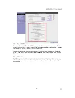
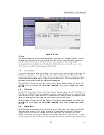
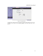
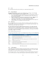
Figure 24 (Ping test) 


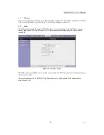
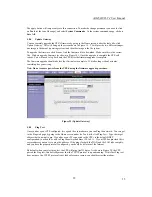
4.8.6 Modem 

Test 

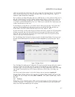
The Modem Test is used to check whether your Modem is properly connected to the WAN Network. This 
test may take a few seconds to complete. To perform the test, select your connection from the list and press 
the Test button.  Before running this test, make sure you have a valid DSL link; if the DSL link is not 
connected, this test will always fail. 
 
Also the DSLAM must support this feature; not all DSLAMs have F4 and F5 support.


4.9 Status 

The Status section allows you to view the Status/Statistics of different connections and interfaces  

4.9.1 Network 

Statistics 

Select to view the Statistics of different interfaces - Ethernet/USB/DSL. 
 

4.9.2 Connection 

Status 

Select to view the Status of different connections. 
 

4.9.3 DHCP 

Clients 

Select to view the list of DHCP clients. 


4.9.4 Modem 

Status 

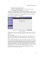
Select to view the Status and Statistics of your broadband (DSL) connection. 
 

4.9.5 Product 

Information 

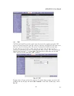
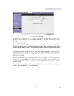
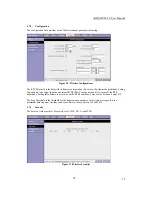
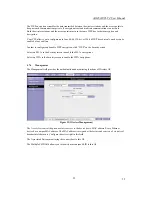
You can display the CPE’s driver and run-time information by going to the 

Hom

e screen, under the 

Status


title, click Product Information.   
 

Summary of Contents for AAM6020VI-T4

Page 1: ...AAM6020VI T4 CPE User Manual AAM6020VI T4 UserManual Rev 1 02 Version date January 11 2005 ...

Page 2: ...indows NT 4 0 11 3 2 6 Assigning IP to your PC automatically by DHCP 11 4 Setting up your CPE 12 4 1 Log into your CPE 12 4 2 Home screen 12 4 3 Setup 13 4 3 1 Wide Area Network connection 13 4 3 2 Local Area Network connection 14 4 4 Configuring the WAN 14 4 4 1 New Connection 14 4 4 2 Modify an Existing Connection 19 4 4 3 Modem setup 19 4 5 Configuring the LAN 19 4 5 1 Enable Disable DHCP 19 4 ...

Page 3: ...t 36 4 9 Status 36 4 9 1 Network Statistics 36 4 9 2 Connection Status 36 4 9 3 DHCP Clients 36 4 9 4 Modem Status 36 4 9 5 Product Information 36 4 9 6 System Log 37 5 Appendix A Troubleshooting 38 5 1 The CPE is not functional 38 5 2 I can t connect to the CPE 38 5 3 The LEDs blink in a sequential pattern 38 5 4 The DSL Link LED continues to blink but does not go solid 39 5 5 The DSL Link LED is...

Page 4: ... are automatically configured Configurable as a DHCP Server on Your Network Compatible with virtually all standard Internet applications Industry standard and interoperable DSL interface Simple web based status page displays a snapshot of your system configuration and links to the configuration pages Downloadable flash software upgrades Support for up to 8 Permanent Virtual Circuits PVC Support fo...

Page 5: ...interface To reset the CPE simply press the reset button for about 5 10 seconds and release After about 30 seconds the CPE will become operational DSL Line port This is the WAN interface that connects directly to your phone line 2 2 LED description Front panel Power LED On indicates that the power is supplied to the CPE Status LED The Status LED serves two purposes If the LED is continuously lit t...

Page 6: ...DSL link is established and active Flashing Trying to create an ADSL connection Off No ADSL link TEST Blue Device in test mode LAN 1 4 Blue On LAN link is established Flashing Data transfer at LAN connection Off No LAN link WLAN Blue On WLAN is service Off No WLAN in service of device Table 1 Front Panel LEDs Parts List In addition to this document your AAM6020VI T4 should come with the following ...

Page 7: ...rear panel of the device and connect the other end of the line to the wall phone jack directly or to an optional POTS splitter If you use a POTS splitter to connect a telephone to the same wall jack as the CPE follow the instructions that came with the splitter 3 1 2 Connect the computers or a LAN You can use the included Ethernet cable to connect your computer directly to the CPE Attach one end o...

Page 8: ...is labeled Local Area Connection The Local Area Connection dialog box is displayed with a list of currently installed network items 4 Ensure that the check box to the left of the item labeled Internet Protocol TCP IP is checked and click on Figure 3 7 Network Connections in Windows XP Figure 3 8 Local Area Connection Properties in Windows XP 5 In the Internet Protocol TCP IP Properties dialog box ...

Page 9: ...nternet Protocol TCP IP Properties dialog box click in the radio button labeled Use the following IP address and type 192 168 1 x where x is any number between 2 and 254 and 255 255 255 0 in the IP address field and Subnet Mask field respectively 12 Click on twice to confirm and save your changes and then close the Control Panel 3 2 3 Windows Me 1 In the Windows task bar click on the Start button ...

Page 10: ...an skip to Step 9 3 If TCP IP does not appear as an installed component click on The Select Network Component Type dialog box appears 4 Select Protocol and then click The Select Network Protocol dialog box appears 5 Click on Microsoft in the Manufacturers list box and then click TCP IP in the Network Protocols list box 6 Click to return to the Network dialog box and then click again You may be pro...

Page 11: ...ation 6 Click on to continue and then click on if prompted to restart your computer 7 After restarting your PC open the Control Panel window and then double click on the Network icon 8 In the Network dialog box click on the Protocols tab 9 In the Protocols tab select TCP IP and then click on 10 In the Microsoft TCP IP Properties dialog box click in the radio button labeled Use the following IP add...

Page 12: ...ou access the router and instead of getting a login screen the browser instead displays a login redirection screen you should check your browser s setting and verify that JavaScript support is enabled Also if you do not get the screen shown in Figure 1 you may need to delete your temporary Internet files basically flush the cached web pages Figure 1 Log in Screen 4 2 Home screen The first screen F...

Page 13: ...oncepts that you should be familiar with on how your new router works Please take a moment to familiarize yourself with these concepts as it should make the configuration much easier Figure 3 Setup page 4 3 1 Wide Area Network connection On the other side of the router is where your Wide Area Network WAN connection also referred to as a broadband connection This WAN connection is different for eve...

Page 14: ... RFC 2364 PPPoA RFC2516 PPPoE Static Bridged CLIP 4 4 1 New Connection A new connection is basically a virtual connection Your CPE can support up to 8 unique with different vpi vci virtual connections If you have multiple different virtual connections you may need to utilize the static and dynamic routing capabilities of the modem to pass data correctly 4 4 1 1 Bridged CPE profile and Connection A...

Page 15: ...Connection The default PPPoE connection setup is displayed At the Type field select PPPoA and the PPPoA connection setup page is displayed figure 5 illustrates a typical PPPoA configuration Give your PPPoA connection a unique name the name must not have spaces and cannot begin with numbers In this case the unique name is called PPPOA1 Select the encapsulation type LLC or VC if you are not sure jus...

Page 16: ... Connection Setup PPPoE is also known as RFC 2516 It is a method of encapsulating PPP packets over Ethernet PPP or Point to Point protocol is a method of establishing a network connection session between network hosts It usually provides a mechanism of authenticating users To configure the CPE for PPPoE click on Setup and then click on New Connection The default PPPoE connection setup is displayed...

Page 17: ...ecified value is 1500 although some DSL ISP providers require a larger value The minimum MRU value is 128 h Enforce MRU Check this box if you experience problems accessing the Internet over a PPPoE connection This feature will force all TCP traffic to conform with PPP MRU by changing TCP Maximum Segment Size to PPP MRU i Debug Enables PPPoE connection debugging facilities Debugging is talked about...

Page 18: ...p Static is used whenever a known static IP is assigned The accompanying information such as the Subnet mask and the CPE should also be specified Up to three Domain Name Server DNS addresses can also be specified These servers would enable you to have access to other web servers Valid IP addresses range is from 0 0 0 0 to 255 255 255 255 To configure the CPE for a Static connection click on Setup ...

Page 19: ...Commands At the system commands page click on Save All 4 4 3 Modem setup To configure the DSL modulation type go to the Home screen Click setup Under WAN Setup select Modem Setup This will bring up the modem setup screen Leave the default value if you are unsure or the DSL ISP did not provide this information For most all cases this screen should not be modified The apply button will temporarily s...

Page 20: ... of minutes the default value is 3600 sec 60 minutes Note If you change the start or end values make sure the values are still within the same subnet as the CPEs IP address Figure 9 DHCP Server configuration In addition to the DHCP server feature the CPE supports the DHCP relay function When the CPE is configured as DHCP server it assigns the IP addresses to the LAN clients When the CPE is configu...

Page 21: ...support 254 users If you want to support a larger number of users you can change the subnet mask but remember The DHCP server is defaulted to only give out 255 IP addresses Further remember that if you change your CPEs IP address and you have DHCP enabled the DHCP configuration must reside within the same subnet The default CPE is the routing device used to forward all traffic that is not addresse...

Page 22: ...s is disabled for all WAN connections The apply button will temporarily save this connection To make the change permanent you need to click on Tools at the top of the page and select System Commands At the system commands page click on Save All 4 6 Advanced The CPE supports a host of advanced features For basic router functionality the user does not need to utilize these advanced features The feat...

Page 23: ...enable UPnP you must first have a WAN connection configured Once a WAN connection is configured from the Home screen click Advanced and under Advanced select UPnP This will bring up the screen shown in Figure 12 You must enable UPnP and then select which connection will utilize UPnP In this case the connection name NEW is enabled Figure 12 UPnP The apply button will temporarily save this connectio...

Page 24: ...vice game or other application select the external connection for example the Internet connection from the Home screen click Advanced and under Advanced select Port Forwarding Next select the computer hosting the service and add the corresponding firewall rule If you want to add a custom application select the User category click New and fill in the port protocols and description for your applicat...

Page 25: ... the Medium and Low priority queues in increments of 10 percent so that that the sum of the weights of these 2 queues is equal to 100 percent Enable IP QoS This field allows you to enable disable IP QoS for the chosen connection Trusted Mode The NSP has two primary modes of operation with regard to queue traffic prioritization Trusted and Un trusted This field allows you to choose the mode Trusted...

Page 26: ...the change permanent you need to click on Tools at the top of the page and select System Commands At the system commands page click on Save All 4 6 5 LAN clients To add a LAN client from the Home screen click Advanced and under Advanced select LAN Clients If DHCP is used all DHCP clients are automatically assigned If a fixed IP address server is on the LAN and you want this server to be visible vi...

Page 27: ...n press the Apply button The Select All select box can also be used to delete the entire filter rule It provides a quick method of selecting all filter rules for deletion The Enable Bridge Filters button allow the user to enable or disable bridge filtering It can be set unset during any add edit delete operation It can also be set unset independently by just pressing the Apply button Figure 15 Bri...

Page 28: ...nnected to more than one network you may need to set up a static route between them A static route is a pre defined pathway that network information must travel to reach a specific host or network You can use static routing to allow different IP domain users to access the Internet through the CPE The New Destination IP is the address of the remote LAN network or host to which you want to assign a ...

Page 29: ...he Direction determines the direction that RIP routes will be updated Selecting In means that the CPE will only incorporate received RIP information Selecting Out means that the CPE will only send out RIP information Selecting both means that the CPE will incorporate received RIP information and send out updated RIP information The protocol is dependent upon the entire network Most networks suppor...

Page 30: ...Figure 18 Dynamic Routing The apply button will temporarily save this connection To make the change permanent you need to click on Tools at the top of the page and select System Commands At the system commands page click on Save All ...

Page 31: ...ult SSID named ADSL_Wireless you can redefine this field the SSID is a unique name to identify the CPE in the Wireless LAN Wireless stations associating to the CPE must have the same SSID Figure 19 Wireless Setup The SSID can be select Hidden in so a station can not obtain the SSID through passive scanning otherwise the AP will be visible The radio frequency used by IEEE 802 1b g Wireless devices ...

Page 32: ...ttribute to be larger than the maximum MSDU MAC service data unit size turns off the RTS handshake Setting this attribute to zero turns on the RTS handshake Enter a value between 0 and 2432 The Frag Threshold is the threshold for the fragmentation boundary for directed messages It is the maximum data fragment size that can be sent Enter a value between 256 and 2432 4 7 3 Security The Security fiel...

Page 33: ...ion click WEP on the Security screen Select on 802 1x in the Security screen to enable the 802 1x encryptions Select on WPA in the Security screen to enable the WPA encryptions 4 7 4 Management The Management field provides the authentication and monitoring functions of Wireless AP Figure 22 Wireless Management The Access List control the given exclusive access to the device host s MAC address Eve...

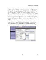
Page 34: ...PoA connections you can select debug if you want to log the connection information This is helpful when trying to debug connection problems The remote log feature will forward all logged information to the remote PC The type of information forwarded to the remote PC depends upon the Log level Each log message is assigned a severity level which indicates how seriously the triggering event affects r...

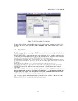
Page 35: ...to complete If it takes longer than 5 minutes something has gone wrong Note Do not remove power from the CPE during the firmware upgrade procedure Figure 23 Update Gateway 4 8 5 Ping Test Once you have your CPE configured it is a good idea to make sure you can Ping the network You can get to the Ping web page by going to the Home screen under the Tools title click Ping Test Type the target address...

Page 36: ...s feature not all DSLAMs have F4 and F5 support 4 9 Status The Status section allows you to view the Status Statistics of different connections and interfaces 4 9 1 Network Statistics Select to view the Statistics of different interfaces Ethernet USB DSL 4 9 2 Connection Status Select to view the Status of different connections 4 9 3 DHCP Clients Select to view the list of DHCP clients 4 9 4 Modem...

Page 37: ...em Log You can display the CPE s log by going to the Home screen under the Status title click System log From here you can view all logged information Depending upon the severity level this logged info will generate log reports to a remote host if remote logging is enabled ...

Page 38: ...g the USB and the Ethernet port at the same time You must only use 1 interface at a time 3 Make sure that your PC and the CPE is on the same network segment The CPE s default IP address is 192 168 1 1 If you are running a Windows based PC you can open a DOS window and type IPCONFIG make sure that the network adapter that is connected to the CPE is within the same 192 168 1 x subnet 4 Also your PC ...

Page 39: ...The DSL Link LED is always off 1 Make sure you have DSL service You should get some kind of information from your ISP which states that DSL service is installed You can usually tell if the service is installed by listening to the phone line you will hear some high pitched noise If you do not hear high pitched noise contact your ISP 2 Verify that the phone line is connected directly to the wall and...

Page 40: ...pose that you want to run a web server or a game server Normal servers like these are blocked from working by the NAT functionality The solution is to isolate the single local computer into a DMZ This makes the single computer look like it is directly on the Internet and others can access this machine Your machine isn t really directly connected to the Internet and it really has an internal local ...

Reviews: