background image

1-8

Chapter 1:  Product introduction

1.6

Motherboard installation

This motherboard uses the Micro ATX form factor.

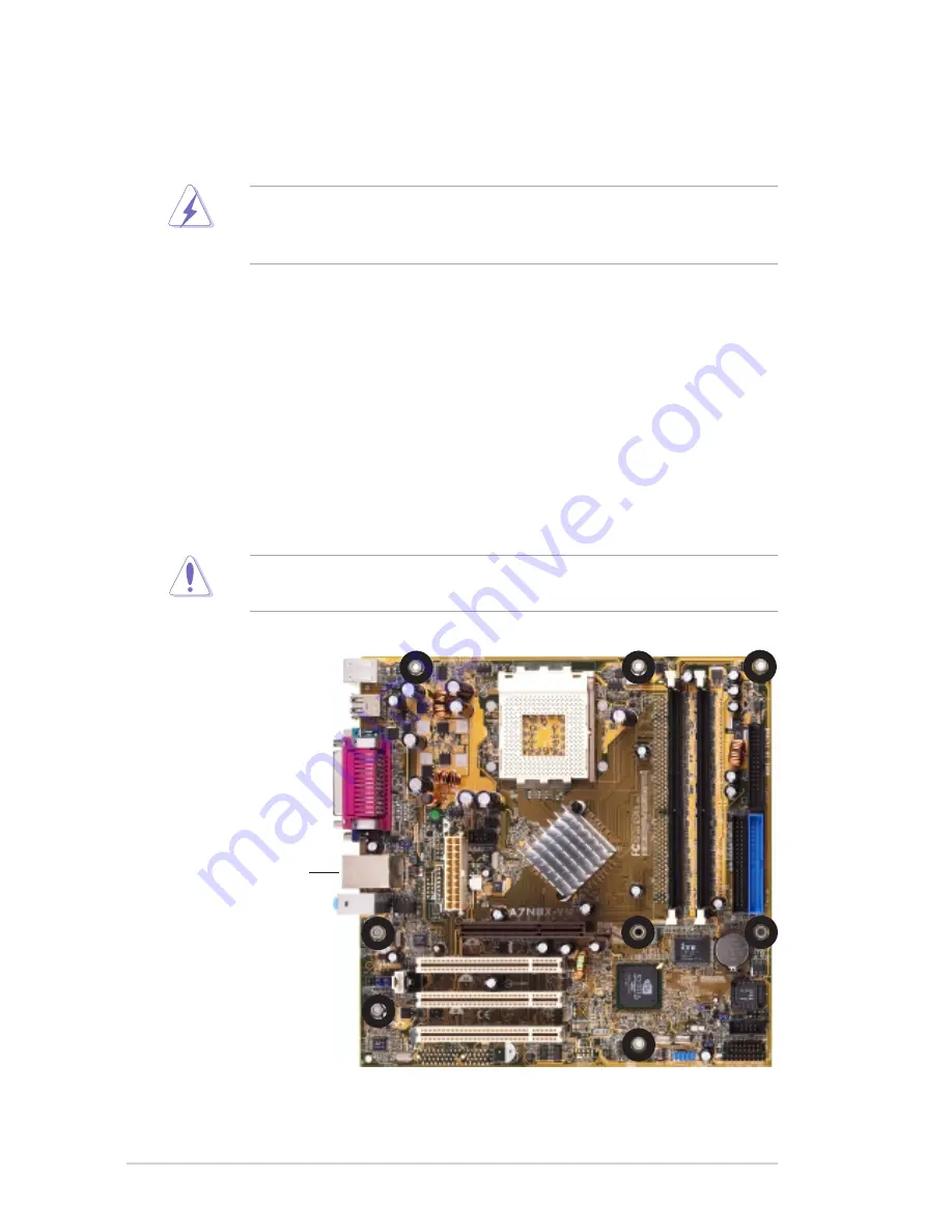
1.6.1 Placement direction

When installing the motherboard, make sure that you place it into the chassis in
the correct orientation. The edge with the external ports goes to the rear part of the
chassis as indicated in the image below.

1.6.2 Screw holes

Place eight (8) screws into the holes indicated by circles to secure the
motherboard to the chassis.

Place this side
towards the rear
of the chassis

Do not overtighten the screws! Doing so may damage the
motherboard.

Unplug the power cord before installing the motherboard. Failure to do
so may cause you physical injury and damage to motherboard
components.

Summary of Contents for A7N8X-VM 400

Page 1: ...Motherboard A7N8X VM 400 User Guide ...

Page 2: ...PARTICULAR PURPOSE IN NO EVENT SHALL ASUS ITS DIRECTORS OFFICERS EMPLOYEES OR AGENTS BE LIABLE FOR ANY INDIRECT SPECIAL INCIDENTAL OR CONSEQUENTIAL DAMAGES INCLUDING DAMAGES FOR LOSS OF PROFITS LOSS OF BUSINESS LOSS OF USE OR DATA INTERRUPTION OF BUSINESS AND THE LIKE EVEN IF ASUS HAS BEEN ADVISED OF THE POSSIBILITY OF SUCH DAMAGES ARISING FROM ANY DEFECT OR ERROR IN THIS MANUAL OR PRODUCT SPECIFI...

Page 3: ...entral Processing Unit CPU 1 10 1 9 System memory 1 11 1 10 Expansion slots 1 12 1 10 1 Configuring an expansion card 1 12 1 10 2 Standard Interrupt Assignments 1 12 1 10 3 AGP slot 1 13 1 10 4 PCI slots 1 13 1 11 Jumpers 1 14 1 12 Connectors 1 16 Chapter 2 BIOS information 2 1 Managing and updating your BIOS 2 2 2 1 1 Creating a bootable floppy disk 2 2 2 1 2 Using AFUDOS to copy the current BIOS...

Page 4: ... 4 3 PCIPnP 2 16 2 5 Power menu 2 18 2 5 1 Power Up Control 2 18 2 5 2 Hardware Monitor 2 20 2 6 Boot menu 2 21 2 6 1 Boot Settings Configuration 2 21 2 6 2 Security 2 23 2 7 Exit menu 2 25 Chapter 3 Software support 3 1 Installing an operating system 3 2 3 2 Support CD information 3 2 3 2 1 Running the support CD 3 2 3 2 2 Drivers menu 3 3 3 2 3 Utilities 3 4 3 2 4 ASUS contact information 3 5 ...

Page 5: ... harmful interference to radio or television reception which can be determined by turning the equipment off and on the user is encouraged to try to correct the interference by one or more of the following measures Reorient or relocate the receiving antenna Increase the separation between the equipment and receiver Connect the equipment to an outlet on a circuit different from that to which the rec...

Page 6: ...your area If you are not sure about the voltage of the electrical outlet you are using contact your local power company If the power supply is broken do not try to fix it by yourself Contact a qualified service technician or your retailer Operation safety Before installing the motherboard and adding devices on it carefully read all the manuals that came with the package Before using the product ma...

Page 7: ...nd software products Refer to the ASUS contact information 2 Optional documentation Your product package may include optional documentation such as warranty flyers that may have been added by your dealer These documents are not part of the standard package About this guide WARNING Information to prevent injury to yourself when trying to complete a task CAUTION Information to prevent damage to the ...

Page 8: ...EC S PDIF in out interface Realtek 8201BL 10 100 Mbps LAN PHY Super I O integrated monitoring of CPU chassis fan rotation and MB CPU temperature 1 x Parallel 1 x Serial COM1 1 x PS 2 Keyboard 1 x PS 2 Mouse 1 x RJ45 port 1 x Audio I O 1 x VGA port 4 x USB 2 0 1 1 1 x USB connector supports additional 2 USB 2 0 ports CPU chassis FAN connectors Chassis intrusion connector 20 pin ATX power connector ...

Page 9: ... WfM2 0 Green PnP TCAV SMBIOS 2 3 ASUS EZ Flash ASUS MyLogo2 PCI 2 2 USB 2 0 DMI 2 0 WOL by PME WOR by PME WO_USB WO_KB MS Device drivers ASUS PC Probe ASUS Update ASUS Screen Saver Adobe Acrobat Reader Anti Virus Utility ASUS A7N8X VM 400 series support CD UltraDMA133 cable FDD cable I O shield User guide Micro ATX form factor 9 6 in x 9 6 in A7N8X VM 400 specifications summary ...

Page 10: ......

Page 11: ...ter 1 This chapter describes the features of the motherboard It includes brief descriptions of the motherboard components and illustrations of the layout jumper settings and connectors Product introduction ...

Page 12: ...400 package for the following items ASUS A7N8X VM 400 motherboard Micro ATX form factor 9 6 in x 9 6 in ASUS A7N8X VM 400 series support CD 40 pin 80 conductor ribbon cable for UltraDMA133 IDE drives Ribbon cable for a 3 5 inch floppy drive Bag of extra jumper caps I O shield User guide 1 3 Special features 400 MHz FSB support The motherboard comes with a Socket 462 that supports the latest 400 MH...

Page 13: ...you to personalize and add style to your system with customizable boot logos See pages 2 22 and 3 5 for details ASUS C O P The ASUS C O P CPU Overheating Protection is a hardware protection circuit that automatically shuts down the system power before temperatures go high enough to permanently damage the CPU ASUS EZ Flash With the ASUS EZ Flash you can easily update the system BIOS even before loa...

Page 14: ...fore you install the motherboard learn about its major components and available features to facilitate the installation and future upgrades Refer to the succeeding pages for the component descriptions 3 4 7 2 6 13 10 5 14 9 8 11 12 1 15 25 18 19 20 21 17 16 23 22 24 ...

Page 15: ...aDMA133 PIO Modes 0 4 IDE devices Both the primary blue and secondary black connectors are slotted to prevent incorrect insertion of the IDE cable Floppy disk connector This connector is for the provided FDD cable for the floppy disk drive One side of the connector is slotted to prevent incorrect insertion of the FDD cable Flash ROM This 4 Mb LPC chip contains the programmable BIOS program Super I...

Page 16: ...he Realtek 8201BL LAN PHY this port allows connection to a Local Area Network LAN through a network hub Line In port light blue This port connects a tape player or other audio sources Line Out port lime This port connects a headphone or a speaker Microphone port pink This port connects a microphone USB 1 2 ports These two 4 pin Universal Serial Bus 2 0 1 1 ports are available for connecting USB de...

Page 17: ...yboard Realtek RTL8201 U46 CHA_FAN Audio Codec Below Mic In Center Line Out Top Line In DDR DIMM2 64 128 bit 184 pin module 2 3 DDR DIMM3 64 128 bit 184 pin module 4 5 PCI 2 PCI 3 Socket 462 24 5cm 9 64in CPU_FAN1 COM1 PARALLEL PORT VGA RJ 45 Top USB1 USB2 Bottom SEC_IDE CLRTC1 USBPW56 USB56 CD1 AUX1 SPDIF1 FPAUDIO CR2032 3V Lithium Cell CMOS Power COM2 PANEL1 CHASSIS1 GAME1 nVidia MCP USBPW34 PWR...

Page 18: ...the external ports goes to the rear part of the chassis as indicated in the image below 1 6 2 Screw holes Place eight 8 screws into the holes indicated by circles to secure the motherboard to the chassis Place this side towards the rear of the chassis Do not overtighten the screws Doing so may damage the motherboard Unplug the power cord before installing the motherboard Failure to do so may cause...

Page 19: ...uching the ICs on components 4 Whenever you uninstall any component place it on a grounded antistatic pad or in the bag that came with the component 5 Before you install or remove any component ensure that the ATX power supply is switched off or the power cord is detached from the power supply Failure to do so may cause severe damage to the motherboard peripherals and or components Onboard LED The...

Page 20: ...to the CPU to prevent overheating A7N8X VM A7N8X VM 400 Socket 462 AMD CPU CPU NOTCH LOCK CPU NOTCH TO INNER CORNER LEVER This motherboard does not support Athlon Duron and other AMD processors with less than 1 GHz core speed Installing the CPU Follow these steps to install a CPU 1 Locate the CPU socket open it by pulling the lever sideways then lift the lever upwards to an angle of 90 100 degrees...

Page 21: ...ory architecture when you install two DDR DIMMs Installing a DIMM 1 Unlock a DIMM socket by pressing the retaining clips outward 2 Align a DIMM on the socket Make sure the notches on the DIMM exactly match the notches in the socket 3 Firmly insert the DIMM into the socket until the retaining clips lock into place A7N8X VM A7N8X VM 400 184 Pin DDR DIMM Sockets 80 Pins 104 Pins Unlocked Retaining Cl...

Page 22: ...but most are already in use Normally six IRQs are free for expansion cards Sometimes IRQs are shared by more than one function in this case IRQ assignments are swapped automatically or adjusted through the BIOS Setup Standard Interrupt Assignments IRQ Standard Function 0 System Timer 1 Keyboard Controller 2 Programmable Interrupt Controller 3 USB Universal Host Controller 4 Communications Port COM...

Page 23: ...to a slot 1 10 2 AGP slot This motherboard has an AGP slot that supports 1 5V AGP 8X cards Note the notches on the card golden fingers to ensure that they fit the AGP slot on your motherboard The AGP slot also supports Digital Video Output DVO interface cards AGP NV DVI for digital display on new generation LCD monitors and projectors A7N8X VM A7N8X VM 400 Accelerated Graphics Port AGP AGP Card wi...

Page 24: ... to pins 1 2 5V by default because not all computers have the appropriate power supply to support this feature The USBPW12 jumper is for the rear USB port USBPW34 and USBPW56 are for the internal USB header that you can connect to front USB ports A7N8X VM A7N8X VM 400 USB Device Wake Up USBPW34 USBPW12 2 3 2 1 5V Default 5VSB USBPW56 2 3 2 1 5V Default 5VSB 2 3 2 1 5V Default 5VSB This feature req...

Page 25: ...l To erase the RTC RAM 1 Turn OFF the computer and unplug the power cord 2 Remove the battery 3 Move the jumper caps from 1 2 to 2 3 momentarily Replace the jumper cap to the original position 1 2 4 Re install the battery 5 Plug the power cord and turn ON the computer 6 Hold down the Del key during the boot process and enter BIOS setup to re enter data A7N8X VM A7N8X VM 400 Clear RTC RAM CLRTC1 No...

Page 26: ...ectors on the motherboard 1 IDE connectors 40 1 pin PRI_IDE SEC_IDE This connector supports the provided UltraDMA133 IDE cable Connect the cable s blue connector to the primary recommended or secondary IDE connector then connect the gray connector to the UltraDMA133 master device hard disk drive and the black connector to the UltraDMA133 slave device hard disk drive A7N8X VM A7N8X VM 400 IDE Conne...

Page 27: ...the future make sure that your new ATX 12 V power supply can provide 8 A on the 12 V lead and at least 1 A on the 5 volt standby lead 5VSB The minimum recommended wattage is 230W or 300W for a fully configured system When the power supply is inadequate the system may become unstable and may experience difficulty powering 4 USB header 10 1 pin USB56 If the USB ports on the rear panel are inadequate...

Page 28: ...USB GAME port module to an open slot in the chassis The GAME MIDI port connects a joystick a game pad for playing games and or MIDI devices for playing or editing audio files A7N8X VM A7N8X VM 400 Game Connector GAME1 5V 5V J2B1 J2CX MIDI_OUT J2CY J2B2 MIDI_IN J1B1 J1CX GND GND J1CY J1B2 5V Do not forget to connect the fan cables to the fan connectors Lack of sufficient air flow within the system ...

Page 29: ... record a chassis intrusion event By default the pins labeled Chassis Signal and Ground are shorted with a jumper cap If you wish to use the chassis intrusion detection feature remove the jumper cap from the pins A7N8X VM A7N8X VM 400 Chassis Alarm Lead CHASSIS1 5VSB_MB Chassis Signal GND Default 8 Front panel audio connectors 10 1 pin FP_AUDIO This connects the front panel audio module that allow...

Page 30: ... card A7N8X VM A7N8X VM 400 Internal Audio Connectors AUX1 White CD1 Black Right Audio Channel Left Audio Channel Ground 10 TV out connector 6 1 pin U46 This connects an audio and TV out port module This connector allows dual display TV VGA or TV DVI with the ASUS AV S and AGP NV DVI cards A7N8X VM A7N8X VM 400 TV Out Connector 1 U46 ASUS AV S The ASUS AV S module is purchased separately ...

Page 31: ...PDIF1 GND 5V SPDIF_IN SPDIF_OUT 1 GND When you input sound for S PDIF IN the LINE_OUT outputs the sound Mute LINE_OUT to impede sound output from S PDIF IN 12 Serial connector 10 1 pin COM2 This connector accommodates a second serial port using an optional serial port module Connect the module cable plug to this connector then install the module into a slot opening at the back of the system chassi...

Page 32: ...r that allows you to hear system beeps and warnings System Management Interrupt 2 pin SMI This connector allows switching to suspend mode or Green mode While is green mode the system activity is instantly decreased to save power and to expand the life of certain system components Reset Switch 2 pin RESET This connector is for the chassis mounted reset switch used for rebooting the system without t...

Page 33: ...Chapter 2 This chapter tells how to change system settings through the BIOS Setup menus Detailed descriptions of the BIOS parameters are also provided BIOS information ...

Page 34: ...op click on Start point to Settings then click on Control Panel b Double click on Add Remove Programs icon from the Control Panel window c Click on the Startup Disk tab then on Create Disk button d Insert a 1 44 MB floppy disk when prompted Follow the succeeding screen instructions to complete the process 2 Copy the original or the latest motherboard BIOS to the bootable floppy disk Important note...

Page 35: ...10 Copyright C 2002 American Megatrends Inc All rights reserved Reading flash 0x0008CC00 9 A afudos oMYBIOS03 rom AMI Firmware Update Utility Version 1 10 Copyright C 2002 American Megatrends Inc All rights reserved Reading flash done A 2 1 2 Using AFUDOS to copy the current BIOS The AFUDOS EXE utility can also be used to copy the current system BIOS settings to a floppy or hard disk The copy can ...

Page 36: ...problems Careless updating may result to more problems with the motherboard 2 1 3 Using AFUDOS to update the BIOS 5 After all tasks are performed AFUDOS utility automatically exits to DOS A AFUDOS afudos ia7nvm400 rom AMI Firmware Update Utility Version 1 10 Copyright C 2002 American Megatrends Inc All rights reserved Reading file done Erasing flash done Writing flash 0x0008CC00 9 DO NOT shutdown ...

Page 37: ...T to display the following 4 Insert the floppy disk that contains the BIOS file If all the necessary files are found in the floppy disk EZ Flash performs the BIOS update process and automatically reboots the system when done User recovery requested Starting BIOS recovery Checking for floppy Floppy found Reading file a7nvm400 rom Completed Start flashing Flashed successfully Rebooting User recovery...

Page 38: ... the optical drive The Drivers menu appears 2 Click the Utilities tab then click Install ASUS Update VX XX XX See page 3 3 for the Utilities menu screen The ASUS Update utility is copied into your system To update the BIOS using the ASUS Update 1 Launch the utility from the Windows desktop by clicking Start Programs ASUS ASUSUpdate ASUSUpdate The ASUS Update initial screen appears 2 Select your de...

Page 39: ...o download Click Next 5 Follow the instructions on the succeeding screens to complete the update process If you selected the option to update the BIOS from a file a window pops up prompting you to locate the file Select the file click Save then follow the screen instructions to complete the update process ...

Page 40: ...er the Setup utility otherwise POST continues with its test routines The Setup program is designed to make it as easy to use as possible It is a menu driven program which means you can scroll through the various sub menus and make your selections among the predetermined choices 2 2 1 BIOS menu bar The top of the screen has a menu bar with the following selections MAIN Use this menu to make changes...

Page 41: ...o the first field End or PgDn Moves the cursor to the last field F5 Resets the current screen to its Setup Defaults F10 Saves changes and exits Setup General help In addition to the Item Specific Help window the BIOS setup program also provides a General Help screen You may launch this screen from any menu by simply pressing F1 or the Alt H combination The General Help screen lists the legend keys...

Page 42: ...ake some time to familiarize yourself with the legend keys and their corresponding functions Practice navigating through the various menus and sub menus If you accidentally make unwanted changes to any of the fields use the set default hot key F5 to load the Setup default values While moving around through the Setup program note that explanations appear in the Item Specific Help window located to ...

Page 43: ...ally detect an IDE hard disk drive If automatic detection is successful Setup automatically fills in the correct values for the remaining fields on this sub menu Configuration options Not Installed Auto CDROM ARMD LBA Large Mode Auto Configures the LBA mode Select Auto to enable LBA mode if the device supports it and the device is not already formatted with LBA Mode disabled Disabled disables the ...

Page 44: ...Self Monitoring Analysis and Reporting Technology system that utilizes internal hard disk drive monitoring technology This parameter is normally disabled because the resources used in the SMART monitoring feature may decrease system performance Configuration options Disabled Enabled Auto 32 bit DataTransfer Mode Disabled Enables you enable or disable 32 bit data transfer mode Configuration option ...

Page 45: ...e 32MB Sets the size of the video frame buffer The settings on this field is valid only for motherboard models with onboard VGA controller Configuration options Auto 8MB 16MB 32MB 64MB 128MB Graphics Aperture Size 64MB Allows you to select the size of mapped memory for AGP graphic data Configuration options 32MB 64MB 128MB 256MB 512MB Disabled 2 4 1 Chipset ...

Page 46: ...rmat PAL Allows you to set the onboard TV out standard Configuration options PAL NTSC 2 4 2 Onboard Devices Configuration Onboard Floppy Controller Enabled Allows you to enable or disable the onboard floppy controller Configuration options Enabled Disabled Serial Port1 Address 3F8 IRQ4 Allows you to set the address for the onboard serial port COM1 Configuration options 3F8 IRQ4 2F8 IRQ3 3E8 IRQ4 2...

Page 47: ...sable the port Configuration options Disabled 200 300 200 330 208 300 208 330 Onboard MIDI Port Disabled Allows you to select the MIDI Port address or to disable the port Configuration options Disabled 200 300 200 330 208 300 208 330 SMBUS Interface Enabled Allows you to enable or disable the SMBus interface Configuration options Enabled Disabled Audio CODEC Interface Auto The BIOS auto detects th...

Page 48: ...default setting 64 for best performance and stability Configuration options 32 64 96 128 160 192 224 248 Allocate IRQ to PCI VGA Yes Select Yes to automatically assign IRQ to PCI VGA card if card requests IRQ If set to No no IRQ is assigned even the card requests an IRQ Configuration options Yes No Palette Snooping Disabled Some non standard VGA cards such as graphics accelerators or MPEG video ca...

Page 49: ...ding the card Configuration options Auto PCI Slot1 PCI Slot2 PCI Slot3 PCI Slot4 PCI Slot5 PCI Slot6 IRQ3 IRQ4 IRQ5 IRQ7 IRQ9 IRQ10 IRQ11 IRQ14 IRQ15 Available Specifies whether an IRQ is reserved or available for use by Legacy ISA devices Configuration options Available Reserved DMA Channel 0 1 3 5 6 7 Available Specifies whether a DMA Channel is reserved or available for use by Legacy ISA device...

Page 50: ...ws the BIOS to select the ACPI state used for System Suspend Configuration options S1 S3 STR S1 POS only Restore on AC Power Loss Power Off When set to Power Off the system goes into off state after an AC power loss When set to Power On the system goes on after an AC power loss When set to Last State the system goes into either off or on state whatever was the system state before the AC power loss...

Page 51: ...vent This feature requires an ATX power supply that provides at least 1A on the 5VSB lead Configuration options Disabled Enabled Ring In Resume Disabled Enables or disables RI to generate a wake event This feature requires an ATX power supply that provides at least 1A on the 5VSB lead Configuration options Disabled Enabled Onboard LAN Resume Disabled Enables or disables the onboard LAN to generate...

Page 52: ...ed xxxxRPM or Disabled Chassis Fan Speed xxxxRPM or Disabled The onboard hardware monitor automatically detects and displays the CPU chassis and power fan speeds in rotations per minute RPM If any of the fans is not connected to the motherboard that field shows 0RPM VCORE Voltage 3 3V Voltage 5V Voltage 12V Voltage The onboard hardware monitor automatically detects the voltage output through the o...

Page 53: ...t devices installed appear in sequence after the list of current boot devices Configuration fields include Floppy Drive IDE Hard Drive ATAPI CD ROM and Other Boot Device 2 6 1 Boot Settings Configuration Quick Boot Enabled Allows BIOS to skip certain tests while booting This will decrease the time needed to boot the system Configuration options Disabled Enabled ...

Page 54: ...mLock key Configuration options On Off Wait for F1 If Error Enabled Sets whether to wait for F1 key to be pressed if an error occurs Configuration options Enabled Disabled Hit Del Message Display Enabled Toggles the display of Press DEL to run Setup Configuration options Enabled Disabled Interrupt 19 Capture Disabled When Enabled it allows option ROMs to trap interrupt 19 This is required by some ...

Page 55: ...alled appears after you have successfully set your password The Supervisor Password item now shows Installed To change the supervisor password follow the same steps as in setting a user password To clear the supervisor password select the Change Supervisor Password then press Enter The message Password Uninstalled appears After you have set a supervisor password the other items appear to allow you...

Page 56: ...hange the user password The User Password item on top of the screen shows the default Not Installed After you have set a password this item shows Installed To set a User Password 1 Select the Change User Password item and press Enter 2 On the password box that appears type a password composed of letters and or numbers then press Enter Your password should have at least six characters 3 Confirm the...

Page 57: ... or F10 from the legend bar to exit If you attempt to exit the Setup program without saving your changes the program prompts you with a message asking if you want to save your changes before exiting Pressing Enter saves the changes while exiting Exit Discard Changes Select this option only if you do not want to save the changes that you made to the Setup program If you made changes to fields other...

Page 58: ...the default values for each of the parameters on the Setup menus When you select this option or if you press F5 a confirmation window appears Select Yes to load default values Select Exit Saving Changes or make other changes before saving the values to the non volatile RAM ...

Page 59: ...Chapter 3 This chapter describes the contents of the support CD that comes with the motherboard package Software support ...

Page 60: ... CD To begin using the support CD insert the CD to your optical drive The CD automatically displays the Drivers menu if Autorun is enabled in your computer If Autorun is NOT enabled in your computer browse the contents of the support CD to locate the file ASSETUP EXE from the BIN folder Double click the ASSETUP EXE to run the CD Click an icon to display more information Click an item to install Be...

Page 61: ...led devices Install the necessary drivers to activate the devices NVIDIA Display Driver Installs the NVIDIA display driver for the onboard VGA NVIDIA nForce Driver Installs the driver for the NVIDIA nForce chipset USB 2 0 Driver Installs the USB 2 0 driver Screen display and driver options may not be the same for other operating system versions ...

Page 62: ...e that you have an Internet connection so you can connect to the ASUS website See page 2 7 for details on how to install and use the ASUS Update Anti virus Utility The anti virus application scans identifies and removes computer viruses View the online help for detailed information AdobeAcrobat Reader Installs the Adobe Acrobat Reader The Acrobat Reader software is for viewing files saved in Porta...

Page 63: ...ASUS A7N8X VM 400 motherboard user guide 3 5 3 2 4 ASUS contact information Click the Contact tab to display the ASUS contact information ...

Page 64: ...3 6 Chapter 3 Software support ...

Reviews: