background image

1-14

Chapter 1: Product Introduction

IRQ assignments for this motherboard

A

B

C

D

E

F

G

H

PCIEX1_1

-

-

-

-

-

-

-

shared

PCIE_X16/X8_1

shared

-

-

-

-

-

-

-

PCI1

-

-

-

-

shared

-

-

-

PCIEX1_2

shared

-

-

-

-

-

-

-

PCIE_X8_2

-

-

-

-

shared

-

-

-

PCI2

-

-

-

-

-

shared

-

-

M.2 PCIE X4 SLOT

-

-

-

-

shared

-

-

-

HD Audio

shared

-

-

-

-

-

-

-

Intel LAN Controller

-

-

shared

-

-

-

-

-

SATA Controller

-

-

-

shared

-

-

-

-

USB 1.1 Controller 1

-

-

shared

-

-

-

-

-

USB 1.1 Controller 2

-

-

-

-

shared

-

-

-

USB 1.1 Controller 3

-

-

-

-

-

-

shared

-

USB 1.1 Controller 4

-

-

shared

-

-

-

-

-

USB 2.0 Controller 1

-

shared

-

-

-

-

-

-

USB 2.0 Controller 2

-

-

-

-

-

shared

-

-

USB 2.0 Controller 3

-

-

-

-

-

-

-

shared

Asmedia USB 3.1 Controller

shared

-

-

-

-

-

-

-

Asmedia USB 3.0 Controller

-

shared

-

-

-

-

-

-


We recommend that you provide suf cient power when running CrossFireX  mode. 


Connect a chassis fan to the motherboard connector labeled CHA_FAN1-3 when 

using multiple graphics cards for better thermal environment. 

VGA configuration

PCI Express 2.0 operating mode

PCIe 2.0 x16/x8_1

PCIe 2.0 x8_2

Single VGA/PCIe card

 x16 (single VGA 

recommended)

N/A

Dual VGA/PCIe card

x8

x8

Summary of Contents for 970 PRO GAMING/AURA

Page 1: ...Motherboard 970 PRO GAMING AURA ...

Page 2: ...pective companies and are used only for identi cation or explanation and to the owners bene t without intent to infringe Offer to Provide Source Code of Certain Software This product contains copyrighted software that is licensed under the General Public License GPL under the Lesser General Public License Version LGPL and or other Free Open Source Software Licenses Such software in this product is...

Page 3: ...Unit CPU 1 5 1 4 System memory 1 9 1 5 Expansion slots 1 12 1 6 Jumpers 1 15 1 7 Connectors 1 17 1 8 Onboard LEDs 1 26 Chapter 2 BIOS Information 2 1 Managing and updating your BIOS 2 1 2 2 BIOS setup program 2 6 2 3 My Favorites 2 10 2 4 Main menu 2 11 2 5 Ai Tweaker menu 2 13 2 6 Advanced menu 2 18 2 7 Monitor menu 2 24 2 8 Boot menu 2 28 2 9 Tool menu 2 33 2 10 Exit menu 2 34 Appendices Notices...

Page 4: ...r Operation safety Before installing the motherboard and adding devices on it carefully read all the manuals that came with the package Before using the product ensure all cables are correctly connected and the power cables are not damaged If you detect any damage contact your dealer immediately To avoid short circuits keep paper clips screws and staples away from connectors slots sockets and circ...

Page 5: ...ns used in this guide To ensure that you perform certain tasks properly take note of the following symbols used throughout this manual DANGER WARNING Information to prevent injury to yourself when trying to complete a task CAUTION Information to prevent damage to the components when trying to complete a task IMPORTANT Instructions that you MUST follow to complete a task NOTE Tips and additional in...

Page 6: ... OS when you want to install 4GB or more memory on the motherboard Due to CPU spec AMD 100 series CPUs support up to DDR3 1066MHz With ASUS design this motherboard can support up to DDR3 1333MHz System Bus Up to 4 8 GT s HyperTransport 3 Multi GPU support Supports NVIDIA Quad GPU SLI Technology Supports AMD Quad GPU CrossFireX Technology Expansion slots 2 x PCI Express 2 0 x16 slots supports x16 x...

Page 7: ...s 2 x Type A at back panel ASMedia USB 3 0 controller 2 x USB 3 0 port s 2 at mid board AMD SB950 controller 14 x USB 2 0 port s 8 at back panel black 6 at mid board Internal I O connectors 1 x 19 pin USB 3 0 2 0 connector supports additional 2 USB 3 0 2 0 port 3 x USB 2 0 1 1 connectors support additional 6 USB 2 0 1 1 ports 1 x System panel header 1 x Front panel audio connector AAFP 6 x SATA 6 ...

Page 8: ...ing control Back panel I O ports 1 x PS 2 keyboard mouse combo port 1 x optical SPDF out 1 x LAN RJ45 port 2 x USB 3 1 ports 2 x Type A Red 8 x USB 2 0 ports 8 channel audio I O ports BIOS features 64 Mb Flash ROM UEFI BIOS PnP DMI2 0 WfM2 0 SM BIOS 2 7 ACPI 2 0a Multi language BIOS ASUS EZ Flash 2 F12 PrintScreen F3 Shortcut Function and ASUS DRAM SPD Serial Presence Detect memory information Man...

Page 9: ...tic pad or in the bag that came with the component Before you install or remove any component ensure that the ATX power supply is switched off or the power cord is detached from the power supply Failure to do so may cause severe damage to the motherboard peripherals or components 1 2 Motherboard overview Before you install the motherboard study the con guration of your chassis to ensure that the m...

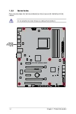
Page 10: ...ion Place this side towards the rear of the chassis 1 2 2 Screw holes Place nine 9 screws into the holes indicated by circles to secure the motherboard to the chassis Do not overtighten the screws Doing so can damage the motherboard ...

Page 11: ...ASUS 970 PRO GAMING AURA 1 3 1 2 3 Motherboard layout ...

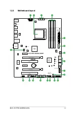
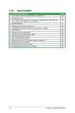
Page 12: ...1 20 4 DDR3 DIMM slots 1 9 5 USB 3 0 connector 20 1 pin USB3_12 1 22 6 AMD SB950 Serial ATA 6 0Gb s connector SATA6G_1 6 black 1 23 7 M 2 Socket 3 1 25 8 Standby Power LED SB_PWR 1 26 9 System panel connector 20 5 pin PANEL 1 24 10 Overclocking Jack 8 1 pin OCJ 1 16 11 Clear RTC RAM 3 pin CLRTC 1 19 12 USB 2 0 connector 10 1 pin USB910 USB1112 USB1314 1 22 13 TPM connector 14 1 pin TPM 1 21 14 Ser...

Page 13: ...I Athlon II Sempron 100 Series Processors Unplug all power cables before installing the CPU The AM3 socket has a different pinout from the AM2 AM2 socket Ensure that you usd a CPU designed for the AM3 socket The CPU ts in only one correct orientation DO NOT force the CPU into the socket to prevent bending the pins and damaging the CPU ...

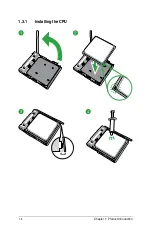
Page 14: ...1 6 Chapter 1 Product Introduction 1 3 1 Installing the CPU ...

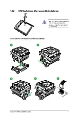
Page 15: ... AURA 1 7 1 3 2 CPU heatsink and fan assembly installation To install the CPU heatsink and fan assembly Apply the Thermal Interface Material to the CPU heatsink and CPU before you install the heatsink and fan if necessary ...

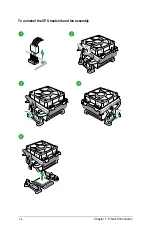
Page 16: ...1 8 Chapter 1 Product Introduction To uninstall the CPU heatsink and fan assembly ...

Page 17: ...odule DIMM sockets A DDR3 module is notched differently from a DDR or DDR2 module DO NOT install a DDR or DDR2 memory module to the DDR3 slot Recommended memory configurations To prevent system instability either install DDR3L DIMMs or DDR3 DIMMs with voltage lower than 1 5V Channel Sockets Channel A DIMM_A1 DIMM_A2 Channel B DIMM_B1 DIMM_B2 ...

Page 18: ...e same CAS latency For optimal compatibility we recommend that you install memory modules of the same version or date code D C from the same vendor Check with the retailer to get the correct memory modules Due to the memory address limitation on 32 bit Windows OS when you install 4GB or more memory on the motherboard the actual usable memory for the OS can be about 3GB or less For effective use of...

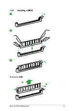
Page 19: ...ASUS 970 PRO GAMING AURA 1 11 To remove a DIMM 1 4 3 Installing a DIMM ...

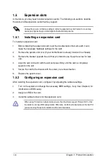
Page 20: ... expansion card After installing the expansion card con gure it by adjusting the software settings 1 Turn on the system and change the necessary BIOS settings if any See Chapter 2 for information on BIOS setup 2 Assign an IRQ to the card 3 Install the software drivers for the expansion card When using PCI cards on shared slots ensure that the drivers support Share IRQ or that the cards do not need...

Page 21: ...ASUS 970 PRO GAMING AURA 1 13 1 5 3 PCI Express 2 0 slots Slot No Expansion slot PCIe 2 0 x1_1 slot PCIe 2 0 x16 x8_1 slot PCI 1 PCIe 2 0 x1_2 slot PCIe 2 0 x8_2 slot PCI 2 ...

Page 22: ...hared USB 1 1 Controller 4 shared USB 2 0 Controller 1 shared USB 2 0 Controller 2 shared USB 2 0 Controller 3 shared Asmedia USB 3 1 Controller shared Asmedia USB 3 0 Controller shared We recommend that you provide suf cient power when running CrossFireX mode Connect a chassis fan to the motherboard connector labeled CHA_FAN1 3 when using multiple graphics cards for better thermal environment VGA...

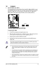
Page 23: ... 4 Hold down the Del key during the boot process and enter BIOS setup to reenter data If the steps above do not help remove the onboard battery and short the two pins again to clear the CMOS RTC RAM data After clearing the CMOS reinstall the battery You do not need to clear the RTC when the system hangs due to overclocking For system failure due to overclocking use the CPU Parameter Recall C P R f...

Page 24: ...ng boot failure Slow Mode Slow Mode is employed during LN2 benching Some processors have a small optimum temperature range to run at their highest frequency Temperatures that fall outside this band may yield instability For example a processor may need to operate at 80 C under load and only 75 C when idle to maintain stability at 5GHz At lower frequencies the CPU s temperature tolerance increases ...

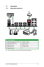
Page 25: ...l connectors 1 PS 2 Keyboard Mouse combo port 6 USB 2 0 ports 34 2 Optical S PDIF OUT port 7 USB 2 0 ports 12 3 LAN RJ 45 port 8 USB 3 1 ports 4 USB 2 0 ports 78 9 Audio I O ports 5 USB 2 0 ports 56 and Refer to the tables on the next page for LAN port LEDs and audio port definitions ...

Page 26: ...SB 3 0 driver installation The plugged USB 3 0 device may run on xHCI or EHCI mode depending on the operating system s setting USB 3 0 devices can only be used for data storage We strongly recommend that you connect USB 3 0 devices to USB 3 0 ports for faster and better performance from your USB 3 0 devices Audio 2 4 6 or 8 channel configuration Port Headset 2 channel 4 channel 6 channel 8 channel...

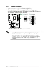
Page 27: ...h higher power output when con guring a system with more power consuming devices or when you intend to install additional devices The system may become unstable or may not boot up if the power is inadequate 1 ATX power connectors 24 pin EATXPWR 8 pin EATX12V These connectors are for ATX power supply plugs The power supply plugs are designed to t these connectors in only one orientation Find the pr...

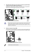
Page 28: ...et to connect the fan cables to the fan connectors Insuf cient air ow inside the system may damage the motherboard components These are not jumpers Do not place jumper caps on the fan connectors The CPU_FAN connector supports a CPU fan of maximum 1A 12 W fan power 3 Serial port connector 10 1 pin COM This connector is for a serial COM port Connect the serial port module cable to this connector the...

Page 29: ...tion audio capability If you want to connect a high de nition front panel audio module to this connector set the Front Panel Type item in the BIOS setup to HD Audio If you want to connect an AC 97 front panel audio module to this connector set the item to AC97 By default this connector is set to HD Audio 5 TPM connector 14 1 pin TPM This connector supports a Trusted Platform Module TPM system whic...

Page 30: ...480Mbps connection speed Never connect a 1394 cable to the USB connectors Doing so will damage the motherboard The USB 2 0 module is purchased separately 7 USB 3 0 connector 20 1 pin USB3_12 These connectors allow you to connect a USB 3 0 module for additional USB 3 0 front or rear panel ports With an installed USB 3 0 module you can enjoy all the bene ts of USB 3 0 including faster data transfer ...

Page 31: ...ASUS 970 PRO GAMING AURA 1 23 8 AMD SB950 Serial ATA 6 0Gb s connectors 7 pin SATA6G_1 6 black These connectors connect to Serial ATA 6 0 Gb s hard disk drives via Serial ATA 6 0 Gb s signal cables ...

Page 32: ...connector The HDD LED lights up or ashes when data is read from or written to the HDD System warning speaker 4 pin SPEAKER This 4 pin connector is for the chassis mounted system warning speaker The speaker allows you to hear system beeps and warnings ATX power button soft off button 2 pin PWR_SW This connector is for the system power button Pressing the power button turns the system on or puts the...

Page 33: ...SUS 970 PRO GAMING AURA 1 25 10 M 2 Socket 3 The M 2 Socket 3 with M Key supports type 2242 22mm x 42mm 2260 22mm x 60mm and 2280 22mm x 80mm PCIe interface storage devices M 2 only supports data storage ...

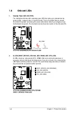
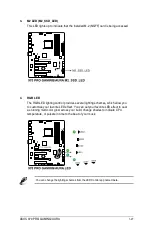
Page 34: ...able before removing or plugging in any motherboard component The illustration below shows the location of the onboard LED 2 Q LEDs BOOT_DEVICE_LED VGA_LED DRAM_LED CPU_LED Q LEDs check key components CPU DRAM VGA card and booting devices in sequence during motherboard booting process If an error is found the corresponding LED ashes until the problem is solved This user friendly design provides an...

Page 35: ... lighting control provides several lighting schemes which allow you to customize your favorite LED effect You can set your favorite LED effect to cast a stunning multi color glow across your build change shades to indicate CPU temperature or pulsate in time to the beat of your music You can change the lighting schemes from the LED Control app named Aura ...

Page 36: ...1 28 Chapter 1 Product Introduction ...

Page 37: ......

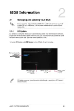
Page 38: ...Z Flash Utility and press Enter 3 Press Tab to switch to the Drive eld 4 Press the Up Down arrow keys to nd the USB ash disk that contains the latest BIOS then press Enter 5 Press Tab to switch to the Folder Info eld 6 Press the Up Down arrow keys to nd the BIOS le then press Enter to perform the BIOS update process Reboot the system when the update process is done This function supports USB ash d...

Page 39: ...le When found the utility reads the BIOS le and enters ASUS EZ Flash 3 utility automatically 4 The system requires you to enter BIOS Setup to recover BIOS settings To ensure system compatibility and stability we recommend that you press F5 to load default BIOS values DO NOT shut down or reset the system while updating the BIOS Doing so can cause system boot failure 2 1 4 ASUS BIOS Updater ASUS BIO...

Page 40: ...elect boot device ESC to boot using defaults 4 When the booting message appears press Enter within ve 5 seconds to enter FreeDOS prompt Welcome to FreeDOS http www freedos org C d D 5 On the FreeDOS prompt type d then press Enter to switch the disk from Drive C optical drive to Drive D USB ash drive ISOLINUX 3 20 2006 08 26 Copyright C 1994 2005 H Peter Anvin A Bootable DVD CD is detected Press EN...

Page 41: ... press Up Down or Home End keys to select the BIOS le and press Enter 4 After the BIOS Updater checks the selected BIOS le select Yes to con rm the BIOS update 5 Select Yes then press Enter When BIOS update is done press ESC to exit BIOS Updater 6 Restart your computer DO NOT shut down or reset the system while updating the BIOS to prevent system boot failure Ensure to load the BIOS default settin...

Page 42: ... program Use the BIOS Setup program to update the BIOS or con gure its parameters The BIOS screens include navigation keys and brief online help to guide you in using the BIOS Setup program Entering BIOS Setup at startup To enter BIOS Setup at startup Press Delete or F2 during the Power On Self Test POST If you do not press Delete or F2 POST continues with its routines Entering BIOS Setup after PO...

Page 43: ...t the display language system performance mode and boot device priority To access the Advanced Mode click Exit Advanced Mode then select Advanced Mode or press F7 for the advanced BIOS settings The default screen for entering the BIOS setup program can be changed Selects the boot device priority Displays the system properties of the selected mode Normal mode Selects the boot device priority Loads ...

Page 44: ...tus and changing the fan settings Boot For changing the system boot con guration Tool For con guring options for special functions Exit For selecting the exit options and loading default settings Advanced Mode The Advanced Mode provides advanced options for experienced end users to con gure the BIOS settings The gure below shows an example of the Advanced Mode To access the EZ Mode click Exit then...

Page 45: ...reen when there are items that do not t on the screen Press the Up Down arrow keys or Page Up Page Down keys to display the other items on the screen Navigation keys At the bottom right corner of the menu screen are the navigation keys for the BIOS setup program Use the navigation keys to select items in the menu and change the settings General help At the top right corner of the menu screen is a ...

Page 46: ...m 2 Press F4 on your keyboard or right click on your mouse to add the item to My Favorites page You cannot add the following items to My Favorites Items with submenu options User con gurable items such as language and boot device order Con guration items such as Memory SPD Information system time and date 2 3 My Favorites MyFavorites is your personal space where you can easily save and access your...

Page 47: ...options Con guration options English Español System Date Day xx xx xxxx Allows you to set the system date System Time xx xx xx Allows you to set the system time Security The Security menu items allow you to change the system security settings If you have forgotten your BIOS password erase the CMOS Real Time Clock RTC RAM to clear the BIOS password See section Jumpers for information on how to eras...

Page 48: ...Enter when prompted to create con rm the password After you clear the password the Administrator Password item on top of the screen shows Not Installed User Password If you have set a user password you must enter the user password for accessing the system The User Password item on top of the screen shows the default Not Installed After you set a password this item shows Installed To set a user pas...

Page 49: ...can cause the system to malfunction The con guration options for this section vary depending on the CPU and DIMM model you installed on the motherboard Current CPU Speed xxxxMHz Displays the current CPU speed Target CPU Speed xxxxMHz Displays the target CPU speed Current Memory Frequency xxxxMHz Displays the current memory frequency Current NB Frequency xxxxMHz Displays the current NB frequency Cu...

Page 50: ...d Enabled Memory Frequency Auto Allows you to set the memory operating frequency Con guration options Auto DDR3 800MHz DDR3 1066MHz DDR3 1333MHz DDR3 1600MHz DDR3 1866MHz DDR3 2133MHz DDR3 2400MHz Selecting a very high memory frequency may cause the system to become unstable If this happens revert to the default setting CPU NB Frequency Auto Allows you to set the ratio between the NB in CPU Clock ...

Page 51: ...therboard DRAM Timing Control The sub items in this menu allow you to set the DRAM timing control features Use the and keys to adjust the value To restore the default setting type auto using the keyboard and press Enter Changing the values in this menu may cause the system to become unstable If this happens revert to the default settings DRAM Driving Control The sub items in this menu allow you to...

Page 52: ... 120 130 CPU Power Phase Control Standard Phase number is the number of working VRM phase Increasing phase number under heavy system loading to get more transient and better thermal performance Reducing phase number under light system loading to increase VRM ef ciency Standard Proceeds phase control depending on the CPU loading Optimized Loads the ASUS optimized phase tuning pro le Extreme Proceed...

Page 53: ...the CPU NB Offset voltage Use the or to adjust the value The values range from 0 006250V to 0 700000V with an interval of 0 06250V The following item appears only when you set CPU Voltage Frequency to Manual VRM Fixed Frequency Mode 200 This item allows you to set a higher frequency for a quicker transient response speed Use the or to adjust the value The values range from 200 KHz to 400 KHz with ...

Page 54: ... 2 200000V to 2 800000V with a 0 006250V interval DRAM Voltage Auto Allows you to set the DRAM voltage Use the or to adjust the value The values range from 1 200000V to 2 200000V with a 0 006250V interval NB Voltage Auto Allows you to set the Northbridge voltage Use the or to adjust the value The values range from 1 100000V to 1 250000V with a 0 006250V interval NB HT Voltage Auto Allows you to se...

Page 55: ...hown in submenu may be different due to the CPU you installed Cool n Quiet Always Enabled This item allows you to enable or disable the Cool n Quiet function Con guration options Disabled by CPU Always Enabled Always Disabled C1E Enabled This item allows your system to utilize the AMD speci c ACPI states to save power consumption Con guration options Disabled Enabled SVM Enabled Disabled Disables ...

Page 56: ...uration options Enabled Disabled The following item appears only when you set SATA Port1 Port4 to RAID Board SATA RAID ROM Legacy ROM This item allows you to select Board SATA RAID ROM Con guration options Disabled Legacy ROM UEFI DRIVER SATA Port5 Port6 AHCI Allows you to set the SATA port 5 6 mode Con guration options AHCI IDE RAID When the SATA Port1 Port 4 and the SATA Port5 Port 6 items are s...

Page 57: ...B devices can be used only for the BIOS setup program Enabled Enables the support for USB devices on legacy operating systems OS Auto Allows the system to detect the presence of USB devices at startup If detected the USB controller legacy mode is enabled If no USB device is detected the legacy USB support is disabled The following item appears only when you set Legacy USB Support to Auto or Enable...

Page 58: ...ables the controller Enabled Enables the Intel LAN controller The following item appears only when you set Intel LAN Controller to Enabled Lntel LAN PXE Option ROM Disabled This item allows you to enable or disable the Rom Help of the Realtek LAN controller Con guration options Disabled Enabled Serial Port Configuration The sub items in this menu allow you to set the serial port con guration Seria...

Page 59: ...DMI Sets to HDMI for HDMI audio output 2 6 6 APM ErP Ready Disabled Allows the BIOS to switch off some power at S5 to get the system ready for ErP requirement When this item is set to Enabled all other PME options will be switched off Con guration options Disabled Enabled Restore AC Power Loss Power Off Power Off The system goes into off state after an AC power loss Power On The system goes into o...

Page 60: ... network stack Con guration options Disabled Enabled The following item appears only when you set Network Stack to Enabled Ipv4 PXE Support Enabled Con guration options Disabled Enabled Ipv6 PXE Support Enabled Con guration options Disabled Enabled 2 6 8 NVMe Configuration You may view the NVMe controller and Drive information if an NVMe device is connected 2 7 Monitor menu The Monitor menu displa...

Page 61: ...Mode Disabled Disable the Q Fan control PWM Mode Enable the CPU Q Fan control feature in PWM mode for 4 pin CPU fan DC Mode Enable the CPU Q Fan control feature in DC mode for 3 pin CPU fan The following items appear only when you set CPU Q Fan Control to PWM Mode or DC Mode CPU_FAN Speed Low Limit 600 RPM This item allows you to disable or set the CPU fan warning speed Con guration options Ignore...

Page 62: ...rning speed Con guration options Ignore 100 RPM 200 RPM 300 RPM 400 RPM 500 RPM 600 RPM Chassis Fan Profile Standard This item allows you to set the appropriate performance level of the chassis fan Standard Sets to Standard to make the chassis fan automatically adjust depending on the chassis temperature Silent Sets to Silent to minimize the fan speed for quiet chassis fan operation Turbo Sets to ...

Page 63: ...ard Sets to Standard to make the chassis fan automatically adjust depending on the chassis temperature Silent Sets to Silent to minimize the fan speed for quiet chassis fan operation Turbo Sets to Turbo to achieve maximum chassis fan speed Manual Sets to Manual to assign detailed fan speed control parameters The following items appear only when you set Water Pump Profile to Manual Water Pump Upper...

Page 64: ...our system to accelerate the boot speed The following items appear only when you set the Fast Boot to Enabled USB Support Partial Initialization Disabled All USB devices will not be available until OS boot up for a fastest POST time Full Initialization All USB devices will be available during POST This process will extend the POST time Partial Initialization For a faster POST time only the USB por...

Page 65: ... the network stack driver from loading during POST Enabled Select to load the network stack driver during POST Next Boot after AC Power Loss Normal Boot Normal Boot Returns to normal boot on the next boot after AC power loss Fast Boot Accelerates the boot speed on the next boot after AC power loss Boot Logo Display Auto Auto Sets the boot logo to display during POST Full Screen Sets the boot logo ...

Page 66: ...e various VGA bootable devices and add on devices for better compatibility Launch CSM Enabled Auto The system automatically detects the bootable devices and the add on devices Enabled For better compatibility enable the CSM to fully support the non UEFI driver add on devices or the Windows UEFI mode Disabled Disable the CSM to fully support the non UEFI driver add on devices or the Windows UEFI mo...

Page 67: ...e Boot keys Save Secure Boot Keys This item allows you to save the PK Platform Keys to a USB storage device PK Management Delete PK This item allows you to delete the PK from your system Once the PK is deleted all the system s Secure Boot keys will not be active Con guration options Yes No Load PK from File This item allows you to load the downloaded PK from a USB storage device The PK le must be ...

Page 68: ... load the downloaded db from a USB storage device Append db from File Allows you to load the additional db from a storage device so that more images can be loaded securely The db le must be formatted as a UEFI variable structure with time based authenticated variable DBX Management Delete the dbx Allows you to delete the dbx le from your system Load dbx from File Allows you to load the downloaded ...

Page 69: ...o le is created Save to Profile Allows you to save the current BIOS settings to the BIOS Flash and create a pro le Key in a pro le number from one to eight press Enter and then select Yes Load from Profile Allows you to load the previous BIOS settings saved in the BIOS Flash Key in the pro le number that saved your CMOS settings press Enter and then select Yes DO NOT shut down or reset the system ...

Page 70: ... you are nished making your selections choose this option from the Exit menu to ensure the values you selected are saved When you select this option or if you press F10 a con rmation window appears Select Yes to save changes and exit Discard Changes Exit This option allows you to exit the Setup program without saving your changes When you select this option or if you press Esc a con rmation window...

Page 71: ...ause harmful interference to radio communications However there is no guarantee that interference will not occur in a particular installation If this equipment does cause harmful interference to radio or television reception which can be determined by turning the equipment off and on the user is encouraged to try to correct the interference by one or more of the following measures Reorient or relo...

Page 72: ... Cet appareil numérique de la Classe B respecte toutes les exigences du Règlement sur le matériel brouilleur du Canada Cet appareil est conforme aux normes CNR exemptes de licence d Industrie Canada Le fonctionnement est soumis aux deux conditions suivantes 1 cet appareil ne doit pas provoquer d interférences et 2 cet appareil doit accepter toute interférence y compris celles susceptibles de provo...

Page 73: ...e ASUS Recycling Takeback Services ASUS recycling and takeback programs come from our commitment to the highest standards for protecting our environment We believe in providing solutions for you to be able to responsibly recycle our products batteries other components as well as the packaging materials Please go to http csr asus com english Takeback htm for detailed recycling information in differ...

Page 74: ...heiten entnehmen Sie bitte der CE Konformitätserklärung Italiano AsusTek Inc con la presente dichiara che questo dispositivo è conforme ai requisiti essenziali e alle altre disposizioni pertinenti alle direttive CE Per maggiori informazioni fate riferimento alla dichiarazione di conformità CE ASUS AsusTek Inc CE CE Hrvatski AsusTek Inc ovim izjavljuje da je ovaj uređaj sukladan s bitnim zahtjevima...

Page 75: ...R INTERNATIONAL America Address 800 Corporate Way Fremont CA 94539 USA Telephone 1 510 739 3777 Fax 1 510 608 4555 Web site http www asus com us Technical Support Support fax 1 812 284 0883 Telephone 1 812 282 2787 Online support http www service asus com ASUS COMPUTER GmbH Germany and Austria Address Harkort Str 21 23 D 40880 Ratingen Germany Fax 49 2102 959911 Web site http www asus com de Onlin...

Page 76: ......
Reviews: