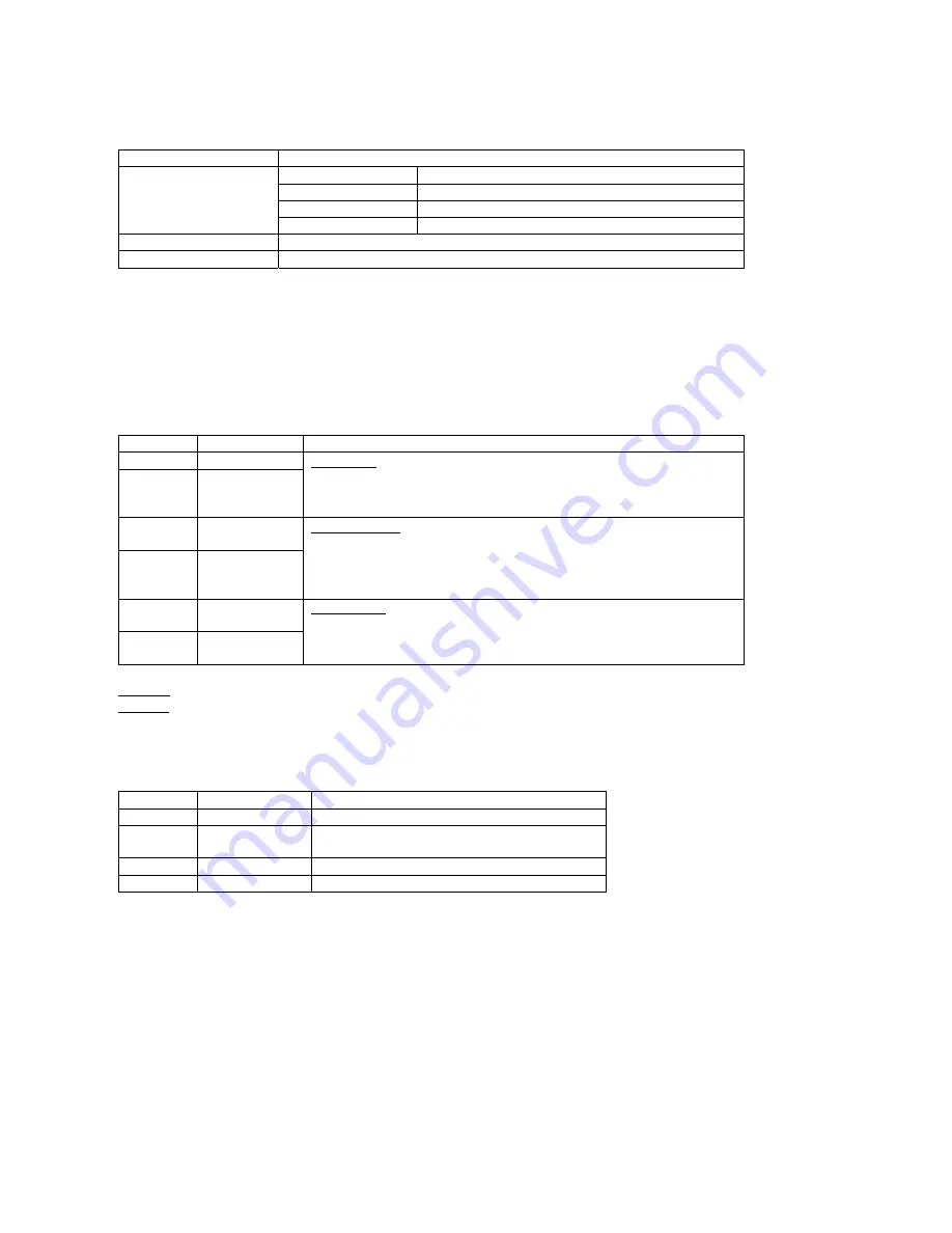
Operating Environment and Parameters
Coolant
Natural cooling or forced convection
Space
Avoid water, dust, oil, frost and corrosive gases
Temperature 0
°
to 50
℃
Humidity
40 to 90%RH
Environment
Vibration 5.9m/s
2
Max
Storage Temp.
-20
℃
to +65
℃
Weight About
0.45kg
3.
Driver Connectors, P1 and P2
The following is a brief description of the two connectors of the driver. More detailed descriptions of the
pins and related issues are presented in sections 4 and 6-9.
Control Signal Connector P1 pins
Pin No.
Signal
Functions
1 Pul
﹢
(+5V)
2
Pul
﹣
(pulse)
Pulse signal: in single pulse(pulse/direction) mode, this input represents pulse
signal, effective for each upward – rising edge; in double pulse mode
(pulse/pulse) this input represents clockwise(CW)pulse. For reliable response,
pulse width should be longer than 3µs.
3 Dir
﹢
(+5V)
4 Dir
﹣
(Dir)
Direction signal: in single-pulse mode, this signal has low/high voltage levels,
representing two directions of motor rotation; in double-pulse mode (set by inside
jumper JMPI), this signal is counter-clock (CCW) pulse, effective on each rising
edge. For reliable motion response, direction signal should be sent to driver 2µs
before the first pulse of a motion direction reversal.
5
Ena+(+5V)
6
Ena- (Ena)
Enable signal: this signal is used for enable/disable, high level for enabling driver
and low level for disabling driver. Usually left unconnected(enabled).
Remark 1: Pul/dir is the default mode; internal jumper JMP1 can be used to switch to CW/CCW double-pulse mode.
Remark 2: Please note motion direction is also related to motor-driver wiring match. Exchanging the connection of two wires for a coil to
the driver will reverse motion direction. (for example, reconnecting motor A+ to driver A- and motor A- to driver A+ will invert motion
direction).
Power connector P2 pins
Pin No.
Signal
Functions
1
Gnd
DC power ground
2
+V
DC power supply, +24VDC to +90VDC, Including
voltage fluctuation and EMF voltage.
3, 4
Phase A
Motor coil A (leads A+ and A-)
5, 6
Phase B
Motor coil B (leads B+ and B-)
4.
Power Supply Selection
It is important to choose the appropriate power supply to make the driver operate properly.
Maximum Voltage Input:
The power Mosfet inside the driver can actually operate 24V to +90VDC, including power input
fluctuation and back EMF voltage generated by motor coils during motor shaft deceleration. Higher
voltage will damage the driver. Therefore, it is suggested to use power supplies with theoretical output
voltage of no more than +85V, leaving room for power line fluctuation and back EMF.
Astrosyn International Technology Ltd, The Old Courthouse, New Rd Ave, Chatham, Kent ME4 6BE, England
Tel: +44(0)1634 815175 Fax: +44(0)1634 826552


