3.
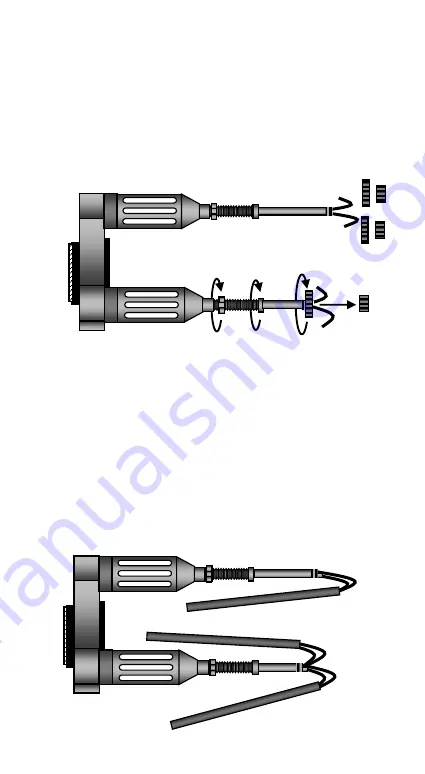
First, pull out (A) the 3 aluminum (VI) collimation nuts
and then unscrew (B) the 3 stainless steel DIN (V) nuts
from the 3 ROTARION PHOTO stainless steel (IV)
arms. Look at the drawing on the next page. Finally,
unscrew the clamping nut (III) and unscrew (D) the 3
arms (IV) to obtain the maximum possible length of
the stainless steel arms (IV).
4.
Insert through the white connecting cable pairs (VII)
of the 3 arms of the ROTARION PHOTO into the 3
black plastic tubes (D) included in the box. These
black plastic tubes are used as guides to facilitate the
passage of the cables in the 2 holes of the handle
screws that you removed in Point 1 of this section and
through the central hole of the ROTARION.
(A)
(B)
(C)
(C)
(D)
Summary of Contents for Rotarion Photo
Page 1: ......


