Astronics Vertical Power Installation And Operating Manual Download Page 6

Page 2 

PPS Installation and Operating Manual

Rev. C.2 (January 19, 2018)

Circuit breaker   While the PPS does not use conventional circuit 

breakers or fuses, the term is very common and herein 

is used to mean the maximum current a circuit will 

draw before faulting.

Fault  

The PPS protects the alternator b-lead and main bus 

wires. When a fault occurs, the PPS turn on the fault 

light. You can then reset or clear the fault, similar to 

resetting a circuit breaker.

1.4 Other Documentation

We provide other documents that should be used in conjunction with this 

manual to help you thoroughly plan a safe and effective electrical system 

for the type of mission you fly. The following documents are available on 

the Documents page in the Help section of the Vertical Power web site 

(

www.VerticalPower.com

), and should be reviewed in conjunction with 

planning your electrical system.

Document


Description

Contactor Wiring 

Overview of the different types of contactors 

used in experimental aircraft, and step by 

step instructions how to wire them properly.

Device Amps 

This document lists the electrical current 

draw of many popular radios, GPS moving 

maps, EFIS displays, lights, and other 

avionics. We maintain it, but contributions 

come from builders. 

Top 10 Wiring Mistakes 

A free, 12-page paper describing the most 

common wiring mistakes and how to get 

started wiring your aircraft.

Additional documentation may also be available on the web site.

2. Operation

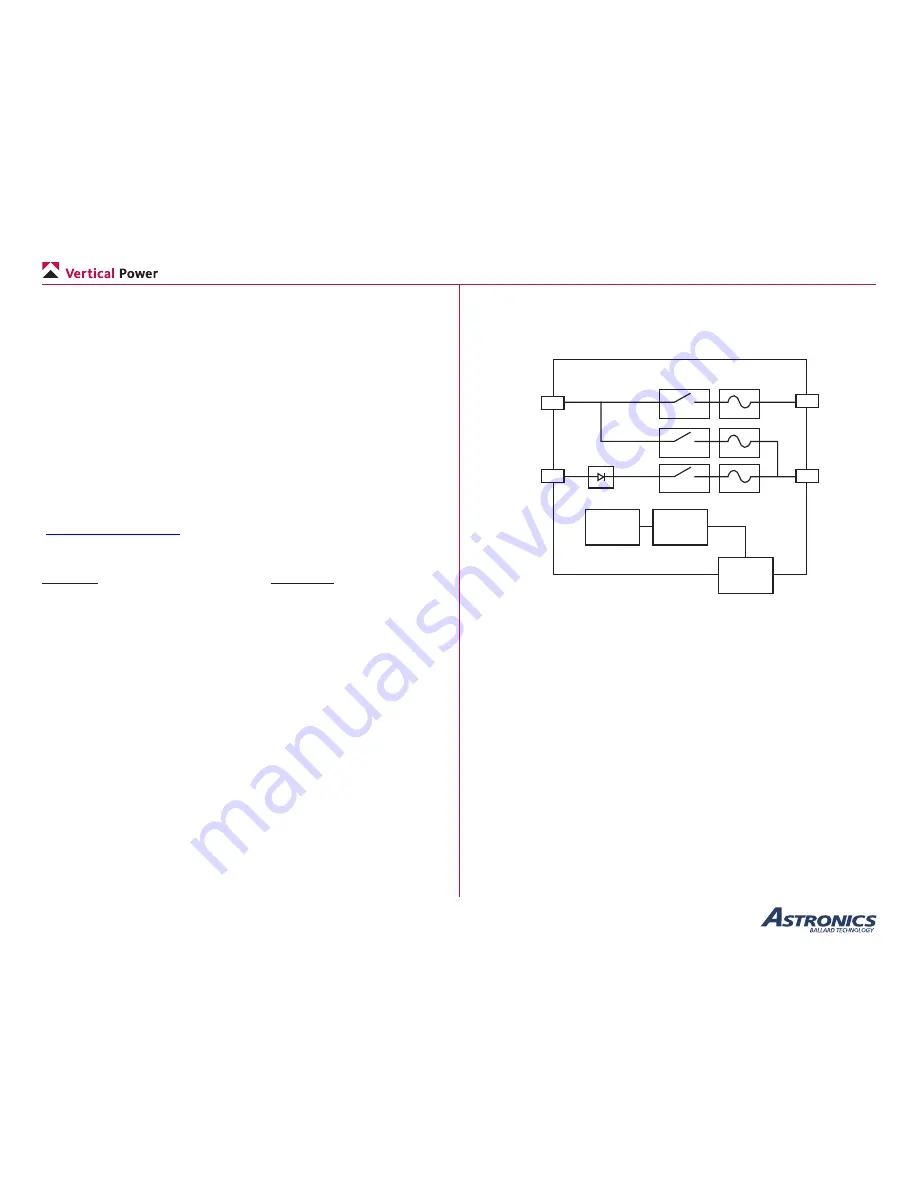
The functional block diagram of the PPS is shown below. The following 

sections explain in detail how each functional block of the PPS operates.

28-pin

Circular 

Connector

Power

Supply

300 A

80 A

80 A

Reverse 

Protection

Fault 

Detection/

Control

Main 

Bus 

Out 

or Main

Power

Starter

Out

Alt 1 & 2

B-Lead 

In

Main

Battery

The Functional Block Diagram of the PPS

2.1 Main Bus Contactor

The main bus contactor allows current to flow to/from the main battery to 

the main power bus. This allows the battery to provide power to the main 

power bus loads and battery charging once the alternator is powering the 

main bus.

For the contactor to be closed, the master switch (MASTER) must be 

closed, the main battery (BATT DIST EN) must be enabled, and there 

must not be an active fault.
The main bus contactor will latch open and indicate a fault (BATT DIST 

FAULT) if the slow-trip current or the instantaneous maximum current of 

320 amps is exceeded. The slow-trip current emulates the trip curve for a 

standard 80 amp slow-blow fuse.
The main bus contactor fault may be reset by either toggling the main 

battery (BATT DIST EN) or master switch (MASTER).

Summary of Contents for Vertical Power

Page 1: ...20180119 Rev C 2 Copyright 2018 by Ballard Technology Inc Primary Power System PPS Primary power control for experimental and light sport aircraft Installation and Operating Manual January 19 2018 Re...

Page 2: ...ts 6 3 3 Alternator Options 6 3 4 Wire Sizes and Circuit Protection 7 3 5 Grounding IMPORTANT 7 3 6 Switch Nomenclature 8 3 7 Current Sensing Shunt 8 4 Installation and Test 4 1 Planning 9 4 1a Tools...

Page 3: ...product is safe reliable and accurate and to determine this product is operating properly after installation DO NOT INSTALL THIS PRODUCT If the aircraft owner pilot and or installer are unwilling to t...

Page 4: ...29 2017 Updates based on product changes incl new pinouts Aug 24 2017 Updated grounding instructions Sep 25 2017 Updated grounding diagram and Table 4 2b Jan 19 2018 Updated current values added Start...

Page 5: ...ndependent batteries alternators battery contactors and a cross tie contactor Multiple PPS units can be used to implement a dual bus architecture Please contact support for more information on dual bu...

Page 6: ...maintain it but contributions come from builders Top 10 Wiring Mistakes A free 12 page paper describing the most common wiring mistakes and how to get started wiring your aircraft Additional document...

Page 7: ...or will latch open if the slow trip current the fast trip current of 1200 amps or the instantaneous maximum current of 1500 amps is exceeded The slow trip current emulates the trip curve for a standar...

Page 8: ...nt fault indication BUS GND ALT DIST FAULT Latched Over current fault indication BUS GND STARTER ACTIVE Starter Active indication BUS GND BATT CURRENT Main Battery current sense 1 mV A relative to 7 5...

Page 9: ...imilar and not because you blindly copied him We believe the most important free advice we can offer is the following CLARIFY YOUR MISSION In this age of gadgets it is all too tempting to add just one...

Page 10: ...lit and sent to individual devices through circuit protection devices fuses and circuit breakers and switches The VP X assumes the role of busses circuit protection and a host of single function modul...

Page 11: ...g IMPORTANT Many people think that the power or positive wire is the most important wire to provide electricity to a device The electrical ground is just as important as electricity must flow the enti...

Page 12: ...drawing more current than the alternator can provide note engine must be running If you set your low voltage alarm on the EFIS at 13 volts then you will get a low voltage alarm if the alternator fail...

Page 13: ...with planning Some items may vary depending on the requirements of your specific installation Crimper insulated terminals 20 AWG Crimper TE Connectivity Hand Crimper 601966 1 or equivalent and TE Conn...

Page 14: ...ay not be needed depending on alternator PPS Wiring Overview with the Vertical Power VP X Aircraft with a remote mounted battery may require the addition of a battery contactor near the battery as sho...

Page 15: ...e connected Maximum wire length 24 in Twist together sense lines on pins 9 and 20 to reduce common mode noise Twist together sense lines on pins 19 and 18 to reduce common mode noise PPS basic install...

Page 16: ...basic installation with the Vertical Power VP X Comprehensive Installation with the Vertical Power VP X The image below details comprehensive PPS connector wiring for an aircraft wired with the Verti...

Page 17: ...airframe 4 2a Mount the PPS The PPS should be mounted to the firewall or other desired location using 4 10 bolts not included A drill punch template is provided on the next page You can print this as...

Page 18: ...Page 14 PPS Installation and Operating Manual Rev C 2 January 19 2018 PPS Mounting Template...

Page 19: ...tor battery starter and grounds 4 2c Control Status Wiring Per your installation plan route wires for the switches and indicators Crimp and install these wires into the circular connector The PPS uses...

Page 20: ...d must connect both pins 26 and 27 to GND maximum wire length 24 inches 26 27 RSVD Reserved do not connect 28 4 3 Ground Test The ground test steps are performed in two parts the first part without th...

Page 21: ...nderstand how to operate the PPS and clear faults This section provides a series of recommended steps which should be incorporated into the overall flight test plan as you deem appropriate Review the...

Page 22: ...put terminal Use multi meter to verify that Master switch input primary or alternate voltage is ground must be below minimum input voltage Use multi meter to verify that Main contactor switch input vo...

Page 23: ...aximum intermittent Alternator Input 80 A maximum continuous Analog Current Monitor Outputs Common mode reference of 7 5 VDC Scale 1 mV Amp Short circuit protected 7 3 Environmental Physical Component...

Reviews: