Astrol Electronic BAT-FLEX Manual Download Page 9


Astrol Electronic AG reserves the right to change specifications without notice


Bat FLEX Manual


9/19


AD-10069-007 Rev. 03 

3.3.


CCCC Overview 

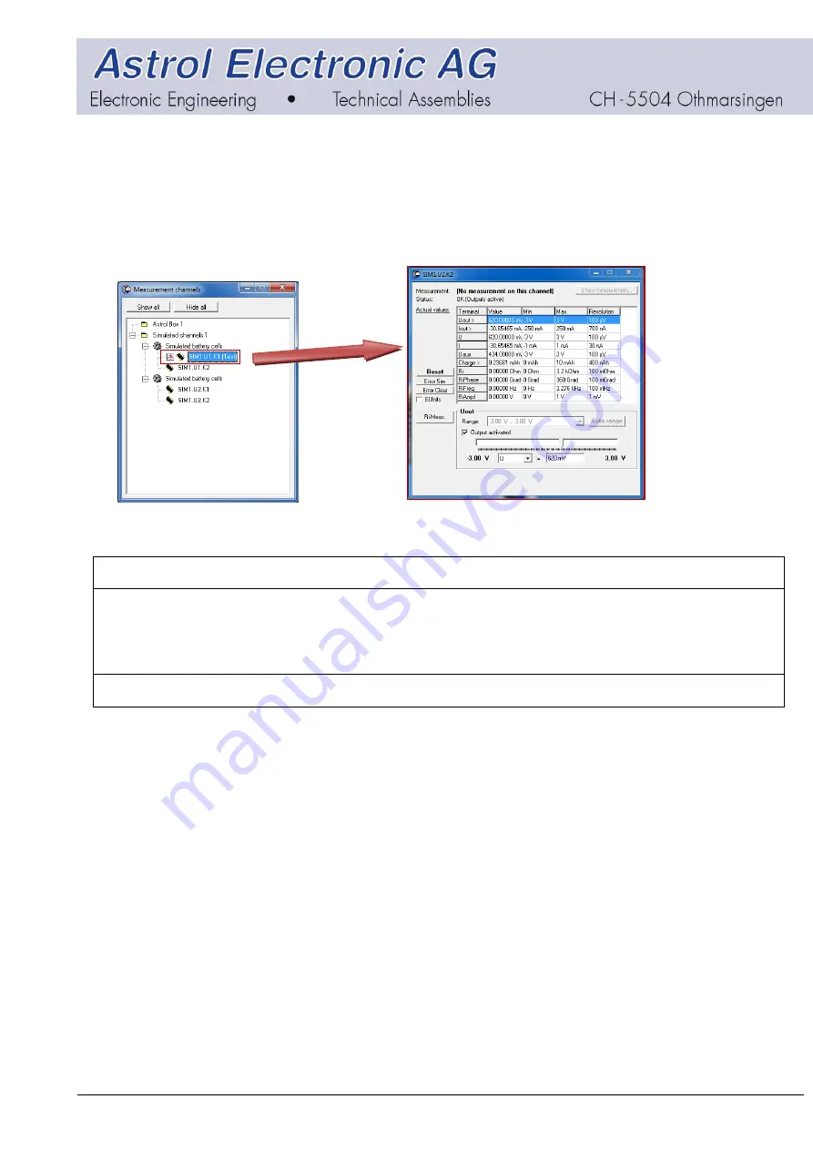
After restarting the application with the communication set up correctly, the devices on the bus should be identified and displayed in 
the device list similar to the screenshot on the right side.


By right click on a channel in the list, the channel window can be opened. 

In that window all measurement values for the selected channel are displayed. Additionally a constant current or a constant voltage 
can be set to the output of the channel for testing purposes. 

Care should be taken to the measured current in this window because the current measurement range doesn't switch automatically to 
constant current mode. The range can be chosen by clicking on „I“ and selecting the appropriate range in the dropdown menu. 

Output Modes 

Constant voltage

: By clicking on „Uout >“ a slider shows up. By enabling the checkbox the value chosen with the slider is sent to the 

device.The device then tries to reach the defined voltage. 

Please note that the voltage is regulated with the device software because the BatFlex Small card outputs are current channels. This 
may lead to a pulsating output waveform when used with inadequate loads. 

Constant current

: Same procedure as with constant voltage. One can click on „Iout >“ and then set the desired output current.  


By right-clicking on the „Astrol-Box“ in the channel-list a window appears with some additional information about the selected device. 
There are also some buttons to calibrate, reset, search for new devices and update the firmware. 


Summary of Contents for BAT-FLEX

Page 1: ...e specifications without notice Bat FLEX Manual 1 19 AD 10069 007 Rev 03 BAT FLEX Manual Rev Remarks changes created checked released 01 Initial ported RT 01 03 13 AST 01 03 13 AST 01 03 13 03 Correct...

Page 2: ...ard 7 2 5 3 BatFlex Small Dual Card 7 3 CCCC Setup 8 3 1 Preparation 8 3 2 Communication Setup 8 3 3 CCCC Overview 9 4 Set up the Measurement Program 10 4 1 Introduction 10 4 2 Measurement Flow 11 4 3...

Page 3: ...cription how to set the device IP can be found in the BatFlex FPGA Card Menu Guide Ethernet User PC 1 2 Direct Connection Please read Appendix A How to set up a static IP for further instructions User...

Page 4: ...ected or unavoidable maintenance of the network could cause measurement data loss 2 3 Card Types The BatFlex Device is designed as amodular System where measurement cards can be replaced whenever the...

Page 5: ...by turning the wheel to the left or to the right Selections are confirmed by pressing the wheel The SD card slot can be used to upgrade the firmware of the device USB and JTAG are for service and deb...

Page 6: ...ice FPGA IMG from SD A new FPGA image will be transferred from the SD card to the device This is a major update which means that the entire software is renewed Firmware from SDCard The FPGA boots up s...

Page 7: ...gnation 2 5 4 1 Specification Channels Details Value Unit Number of channels 8 Pcs Current measurement Details Value Unit Resolution 188 uA 100 pA 750 uA 400 pA 3 mA 1 5 nA 24 mA 12 nA Accuracy full s...

Page 8: ...needs to be restarted On startup the application searches for a viable device on the Network If the device is not yet configured the first action after the main window shows up is to get into the comm...

Page 9: ...esn t switch automatically to constant current mode The range can be chosen by clicking on I and selecting the appropriate range in the dropdown menu Output Modes Constant voltage By clicking on Uout...

Page 10: ...is created by the CCCC Software during a measurement It contains the measurement data recorded by the device Log File log This File contains all the events that took place during the measurement For e...

Page 11: ...en move from position to position during the execution Each step has its unique ID and can be configured with individual parameters It s also possible to jump between the steps by setting conditions t...

Page 12: ...ostatic Step This step implements a galvanostat or current source Its main purpose is to keep the current through the cell constant disregarding changes in the load itself This step offers a condition...

Page 13: ...channel has to be selected After that the measurement window can be opened The measurement window contains control elements to start stop and pause the data recording as well as a table with the curre...

Page 14: ...irst step is a counter step which sets the cycle counter to one The following two steps are galvanostatic steps which charge discharge with a constant current until the defined end voltage is reached...

Page 15: ...Tool offers two main methods to display the data as a CV diagram Current Voltage or as a time dependent diagram There are many customizable parameters to get the best view on the desired data 7 Expor...

Page 16: ...twork card with up to date network drivers Open the Network and Sharing Center This can be found in the Control Panel under Network and Internet A Control Panel can be opened by pressing Windows R the...

Page 17: ...ddress This will activate the input fields One should use the data obtained in the first step to complete the Subnet mask Gateway and the DNS server addresses The computer will change the IP address a...

Page 18: ...e 1 Guard 2 Never connect different guard types the device could be damaged 2 Aux 2 3 Guard 2 4 Guard 2 5 Aux 2 6 Guard 2 7 NC Not connected 8 Guard 1 9 Aux 1 10 Guard 1 11 Guard 1 12 Out 1 13 Guard 1...

Page 19: ...l with serial number 11 2 Inside Type label with serial number on the left side 12 Order code Type Order Code BatFlex Base Device with Reference Card AA 10320 001 Bat Flex Small Dual 8 Channels AA 103...

Reviews: