


OM226142 rev C
44
Minimum battery voltage
326Vdc
Maximum charging voltage
490Vdc
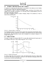
As soon as the battery charging current exceeds a certain threshold (generally 0,08C
10
)
the rectifier switches to BOOST charge (2,4 V/cell for lead acid batteries, 1,55 V/cell for
Ni-Cd batteries) and starts a charging cycle with the first part at constant current as the
voltage increases slowly. When the voltage reaches the boost charge level the current
begins to decrease until it reaches the second threshold (generally 0,03C
10
) and the
rectifier is switched back to FLOATING charge.
During the boost charge mode the battery emits hydrogen owing to the chemical reaction
that also causes the heating of the elements. In order to avoid the over-heating or
excessive consumption of the electrolyte, the microprocessor is equipped with a safety
timer that provides to stop the boost charge in case it exceeds 12 hours. An alarm
indication on the display warns the user that something is wrong with the batteries.
6.11 PARALLEL REDUNDANT CONFIGURATION
Picture 36 – Parallel redundant block diagram
The parallel system consists of “n” (up to 4) units, which are equipped like standard units.
Only the manual bypass can be external and unique for all the units (on request).
On each unit one extra pcb (RPI-BUSCAN), that provides the parallel redundant functions,
is installed.
In addition to the standard functions as uninterruptible power supply, total power control
and protection of the load from mains distortion, the parallel redundant system guarantees
an uninterrupted power supply even in case of an internal failure in one of the UPS units.


