13
INSTALLATION AND OPERATION MANUAL
Do not forget to keep the returning water temperature as high as possible, at least 65°C or even higher!
It is necessary to assure that a thermometer is installed on the returning water pipe, in order to be able to
observe this temperature at any time!
• INSTALLATION OF THE BOILER ROOM
The boiler room should be ventilated. The required air inflow necessary for combustion should be also ensured. For this
purpose, boiler room doors should have ventilation grating or there should be a sufficient gap between the doors and the
floor. If there is no possibility to supply air in from another rooms or the house is very tight, it will be necessary to install an
opening in the exterior wall. The cross-section area of the opening should be at least 0.001 m2/kW.
Place the boiler as close to the flue as possible on a hard concrete levelled basement. Leave at least 600 mm gap between the
backside casing of the boiler and the room wall for boiler servicing and cleaning. The smallest distance between a lateral casing
of the boiler and a building structure is 400 mm. If the building structure is made of flammable materials, this distance should be
doubled. A freely approachable space of at least 800 mm should be then left from the opposite side of the boiler to ensure access
to the backside of the boiler, for its servicing and cleaning. The floor under the boiler, within the distance of 50 cm in front of it and
within the distance of 30 cm around the boiler should be made of inflammable materials. Screw supporting legs onto the base
of the boiler and level the boiler with screw nuts using a level; then connect the heating system circulation pump to the boiler.
The smoke exhaust pipe of the boiler should be connected to the chimney through a metal duct. The internal diameter of
the metal connecting duct should be at least the same as the external diameter of the smoke exhaust pipe of the boiler. To
improve the draught, the connecting duct between the boiler and the chimney should be installed at an inclination towards
the boiler. All junctions should be carefully tightened using a heat-resistant material and insulated using thermal insulation.
If an additional damper is installed between the boiler and the chimney for the draught control purpose,
the damper should not close more than 2/3 of the cross-section area of the opening in its fully closed position.
• REQUIREMENTS FOR THE CHIMNEY
It is recommended to insert acid-resistant stainless steel liner, if the chimney is made from masonry. It improves draught of
the chimney and protects the masonry from destruction due to the impact of condensate. Internal diameter of the liner should
be no less than the external diameter of the smoke exhaust pipe of the boiler. The chimney liner can be round or oval. It is
not recommended to use rectangular-
shaped liner as, due to the temperature
fluctuations, its walls deform, gaps
appear at the element junction points,
through which the condensate falls
on the walls of the bricks chimney.
Additional air is sucked in, which reduces
draught of the chimney. Draught for
each boiler model should correspond
to the referred value of draught in the
table “Technical data”. The liner should
be factory made. Minimum permissible
height of the chimney should be at least
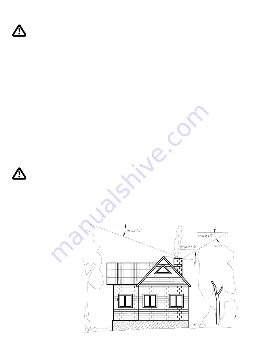
7 m. The top of the chimney should be
above the ridge at least by 0.5m. If the
chimney is further from the ridge than
1m, the angle horizon- the ridge- the
cap of the chimney should consist 10°
Fig. 8 Positioning of a chimney in respect to vicinity objects


