ASTi Telestra Target Operations & Maintenance Manual (Ver. 2, Rev. M)
12
Copyright © 2020 Advanced Simulation Technology inc.
3.5. Connections
After unpacking the Target, connect the power, network, keyboard and monitor cords to the
system as described below. Allow two inches of space to the rear of the Target for connections.
Remove all plastic packaging from the Target before proceeding with the system
installation.
Note: As technology evolves, the
Telestra
Target chassis will continue to change.
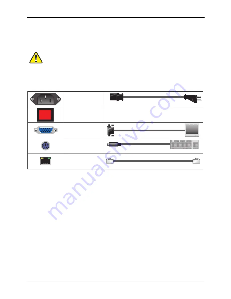
Look for these objects on the rear of the chassis, and connect as appropriate.
Power Cord In
Video Output
Keyboard
Ethernet Jack
Main Power Switch
May not be present on all systems
To chassis
To wall
Connects to monitor's 15-pin D connector
PS/2 connection, may not be purple in color
Each system will have three (3) labeled jacks
RJ-45 connection
To network
x3
Not Included
Remember to switch on the main power switch on the rear of the
Telestra
Target chassis.
3.5.1. Connecting ACENet Devices
The ACENet devices connect to the Target through an Ethernet port connection on the rear panel
of the chassis.
3.5.2. Power Connection
The power cord attachment and the power switch push-button are both located on the rear panel
of the chassis.
3.5.3. Monitor Connection
The monitor can be plugged directly into the Target.
3.5.4. Keyboard Connection
The keyboard connection is a 6-pin mini DIN (PS/2-style) connector on the back of the Target. On
all systems, the Target is configured to boot and operate properly with or without the keyboard
connected.


