6
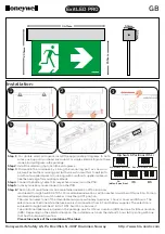
INSTALLATION AND CONNECTION
The installation have to be realized by qualified personnel.
Note:
•
Do not cover the path light optical window with any kind of temperature isolating material.
The path light is protected by a temperature sensor against over-heating. When the
temperature of the flood-path light exceeds 85°C the path light is automatically switched
off.
The power supply has to be connected through the main switch (not included) and protected by a
fuse (not included).
Note:
•
The power supply has to be switched off before installation.
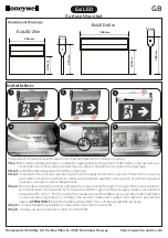
The light has to be connected as described in the table below:
ALOA
FUNCTION
wire color
wire mark
Brown
L
Line 230 Vac
Blue
N
Neutral 230 Vac
Yellow/Green
Earth 230 Vac
Gray
C+
(24 Vdc max.)
Black
C-
CONTROL- (24 Vdc max.)
For basic control of the light the CONTROL wires have to be connected through the momentary
switch (not included) to the power source / 12-24Vdc (not included) by using a 2-pole signal cable
extension (not included).
For DMX512 control optional LXU01 interface can be connected to the CONTROL wires by using a
2-pole signal cable (not included).
Note:
•
When two or more lights are connected in the lighting system the control wires can be
connected in parallel and all the lights then can be controlled by using only one
momentary switch or LXU01 interface.
Earthing
The flood-path light has to be earthed by using a pre-tinned green wire with a yellow stripe a
minimum of 8 AWG (8.36 mm
2
). The wire has to be connected to the path light by the help of one
assembling screw.
Summary of Contents for LAD1800
Page 1: ...ALOA PATH LED LIGHT Operating Instructions...
Page 9: ...9...