background image

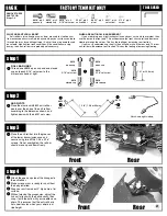
step 4

SHORT OUTDRIVE

Add a small amount of #6591Stealth diff lube to the 
#3904 locknut where shown to help hold it in place. 
Insert the #3904 2-56 locknut into the #3908 short 
outdrive. The nut should fit flat inside the hex 
shape. 

3904

3908

step 3

LONG HUB ASSEMBLY

Insert the thrust assembly into the #3908 long hub.
Add a light coat of #6591 Stealth lube to the long 
hub face where shown.
Place a #3906 diff ring on the hub, lining up the flats 
on the ring and hub.
Insert #3907 bushing into the long hub.

6591

Trim any burrs 
from the inside 
of the gear with 
a hobby knife.

6

step 1

THRUST BALL ASSEMBLY

Hold the #6575 diff bolt with your 5/64" Allen wrench 
and slide one #6573 washer onto the #6575 diff bolt.
Apply a generous amount of #6588 black grease to the 
washer on the side facing away from the bolt head.
Place six #6574 thrust balls into the grease against the #6575 bolt and 
washer. Add the other #6573 washer. The grease will hold the balls in 
place during assembly, sandwiched between the washers.

6575

5/64" Allen wrench

6573

6588

6574

6573

step 2

SPRING

With a pair of pliers, compress the 
#6582 diff spring a few times. 
Slide the spring onto the bolt against 
the thrust assembly. 

6582

6582

thrust assembly

6591

3906

3907

3908

CAUTION!!

Make sure you line up the flats on the diff ring and hub

step 5

DIFFERENTIAL RING GEAR

Trim any burrs from the inside of the gear with a hobby knife.
Add a generous amount of #6591 diff lube to the #3914 ring gear ball holes 
and push in the twelve #6581 diff balls. Then push back in the lube that 
came out.

6581

3914

3914

(grease not shown)

Smear a small amount of diff lube here to 
hold the drive ring in place

spring
washer
balls
diff bolt
washer
Allen wrench

spring
washer
balls
diff bolt
washer
Allen wrench

6591

Summary of Contents for TC3

Page 1: ...atsink Carbide ball Stealth differentials Adjustable caster camber toe in anti squat kickup Several tie rod mounting positions Foam bumper TC3 decal sheet Rear bumper HELPFUL TOOLS NOT REQUIRED Allen drivers straight Allen wrenches with hex shaped handles such as the following made by Associated 6957 050 driver 6958 1 16 driver 6959 5 64 driver 6960 3 32 driver 6961 2 5mm driver Vernier calipers H...

Page 2: ...he word REAR with an arrow indicates which direction is the rear of the car to help keep you oriented 5 The instructions in each step are ordered in the order you complete them so read the words AND follow the pictures The numbers in circles are also in the drawing to help you locate them faster 6 When we refer to left and right sides of the car we are referring to the driver s point of view insid...

Page 3: ...re flush with the top of the arm We will adjust them in step 3 Attach the 3863 front arm rear mount with the F molded into mount see below for location to the chassis with two 6292 6934 screws Attach the 3863 front arm front mount with the F 2 molded into the mount to the 3851 bumper with one 6292 6934 screw Slide the 3866 inner hinge pins through the 3860 3861 front arms Slide the pins with the a...

Page 4: ...O REMOVE THE BALLS Remove flashing so balls are perfectly smooth DO NOT REMOVE 3865 3865 6292 6934 6292 6934 6292 6934 step 3 SETTING DROOP Place the supplied 3987 droop gauge on a flat surface on its edge as shown Rest the bottom of the chassis on the gauge as shown making sure the screws are not resting on the gauge Slide the gauge out so the front arm rests on step 6 With your 3 32 Allen wrench...

Page 5: ... facing away from the bolt head Place six 6574 thrust balls into the grease against the 6575 bolt and washer Add the other 6573 washer The grease will hold the balls in place during assembly sandwiched between the washers 6575 5 64 Allen wrench 6573 6588 6574 6573 step 2 SPRING With a pair of pliers compress the 6582 diff spring a few times Slide the spring onto the bolt against the thrust assembl...

Page 6: ... in opposite directions Then screw in the bolt some more Follow this procedure to check proper alignment of the parts The following note clarfies this READ THE FOLLOWING CAREFULLY As you tighten the diff bolt pay close attention to the feeling when the spring is fully compressed Do not overtighten the bolt When you feel the spring fully compressed loosen the diff bolt 1 2 turn No more no less Afte...

Page 7: ...ar adapter 3919 qty 1 C clip 1 1 RACER KIT ONLY 3977 qty 2 3 16 x 3 8 bearing rubber sealed TEAM F T KITS ONLY 6906 qty 2 3 16 x 3 8 bearing PTFE sealed 1 1 3915 input shaft 3919 pin 3914 drive pinion 3919 small E clip 3917 drive cup 6920 step 10 REAR INPUT SHAFT ASSEMBLY Attach the 3919 C clip to the 3915 rear input shaft We ve included an extra C clip in case you lose one Install the 3919 dowel ...

Page 8: ...one 3919 dowel pin into the input shaft Slide a 3917 drive cup onto the input shaft Tighten it down with one 6920 screw Slide in a 5407 O ring into the 3917 drive cup 3919 3919 pin 3915 rear input shaft 3911 spacer 5407 step 12 REAR INPUT SHAFT ASSEMBLY Slide the 3922 spur gear over the drive cup and align it on the 3917 gear adapter Tighten down the spur gear with two 6288 screws 3922 spur gear 6...

Page 9: ... 6292 6934 6292 6934 step 16 REAR TRANSMISSION ASSEMBLY Install the diff assembly into the lower transmission case Place one end of the 3924 drive shaft into the drive cup on the rear input shaft assembly Install the opposite end of the drive shaft into the front drive cup Set the rear input shaft into place Add a small amount of 6591 diff lube to the front side of the ring gear and pinion 3924 dr...

Page 10: ... the two 7413 screws through the outer holes on the 3881 3882 front shock tower Then thread on the 7260 nuts Attach the 3858 ball ends and 7260 nuts through the lower inner holes on the shock tower Add a 6272 dust cover to the ball ends 6272 qty 4 ball end dust cover 6924 6860 qty 6 4 40 x 3 8 screw 7260 qty 8 4 40 plain nut 7413 qty 4 4 40 x 3 4 screw 3881 3882 qty 1 front shock tower 3895 3896 q...

Page 11: ...er bushings 1 1 1 1 1 1 1 16 050 3965 qty 2 bearing spacer 1 1 1 1 1 1 step 1 MIP CVD ASSEMBLY Spread some Associated 6588 black grease inside the axle hole where shown then on the coupling and insert the coupling into the axle Slide the axle into the dogbone aligning the cross holes Insert the cross pin making sure it is evenly spaced on both sides of the bone Add the MIP thread lock to the set s...

Page 12: ... 2 long special ball end black 7368 qty 2 3 16 axle shim 1 1 RACER KIT ONLY 3977 qty 4 3 16 x 3 8 rubber sealed bearing F T TEAM KITS 6906 qty 4 3 16 x 3 8 PTFE sealed bearing 1 1 7369 qty 2 CVD roll pin 3862 qty 2 5 40 set screw gold 4187 qty 4 washers plastic 3866 qty 2 rear outer hinge pin 1 1 1 1 1 1 1 1 1 16 3876 3977 qty 2 rear hub carrier 1 1 1 1 step 5 REAR HUB CARRIER ASSEMBLY Break throu...

Page 13: ...nium turnbuckle 3879 3880 qty 2 front chassis brace 3879 3880 qty 2 rear chassis brace 6274 qty 12 ball cup 1 1 6923 qty 4 4 40 x 3 4 screw 1 1 6924 6860 qty 8 4 40 x 3 8 screw 1 1 RACER KIT ONLY 3867 qty 6 steel turnbuckle 1 1 1 1 1 16 3 32 LEFT REAR HUB CARRIER SHOWN step 1 TURNBUCKLE ASSEMBLY Twist the 6274 ball cups onto the 1356 blue titanium turnbuckle or 3867 steel turnbuckle until you get ...

Page 14: ...ication that indicates where it goes on the car as shown below step 2 INSTALLING CHASSIS BRACE Mount the 3879 3880 left front and left rear chassis braces with two 6924 6860 screws and one 6923 screw for each brace as shown Repeat step for the right side 2 6924 6860 6923 3879 3880 6923 LR LF BAG G REMOVE THESE PARTS FOR Steps 1 4 TOOLS USED 15 5407 qty 8 red O ring 6465 qty 4 shock piston 2 5423 q...

Page 15: ...p above the shock body Fill The 6428 shock cap about halfway with oil and install onto the body Try to retain as much oil as possible during assembly The shaft will extend out as you tighten the cap down step 4 SETTING THE REBOUND Move the shock shaft in and out a few times an then push it all the way in It should be easy to push the shaft in until the eyelet hits the body Then the shaft should pu...

Page 16: ... qty 1 motor cam 3931 3933 qty 1 motor clamp with heatsink 3934 qty 2 3mm motor screw 4449 qty 2 4 40 locknut 6332 qty 3 battery clip 1 1 RACER TEAM 6917 qty 4 4 40 x 3 8 screw 1 1 6928 qty 1 4 40 x 1 screw 1 1 6916 qty 2 4 40 x 1 2 screw with hole 7336 qty 2 servo mount 7336 offset spacer qty 2 thin qty 2 thick 1 1 7337 qty 4 steel washer 1 1 7673 6934 qty 2 4 40 x 5 16 screw 9180 qty 4 servo hor...

Page 17: ...THE SERVO Mount the servo to the chassis with two 7673 6934 screws Twist 6274 ball cups onto 1356 blue turnbuckle or 3867 steel turnbuckle until you get the dimension shown Use needle nose pliers to attach the link to the ball ends 7673 6934 1 56 in 6274 1356 or 3867 step 3 INSTALL YOUR MOTOR Attach the 3930 3932 motor cam to the optional motor with two 3934 button head motor screws Install the op...

Page 18: ...ough the small hole on top of the mount ESC receiver 6338 3 step 6 BATTERY INSTALLATION Install your battery pack See which figure at left or right best represents your battery orientation Thread on the two 6916 screws Aim the body clip hole across the chassis Add the 3848 foam spacer Add the 3853 3974 battery hold down strap orienting it up or down according to your battery pack design Adjust the...

Page 19: ...heel 3955 qty 4 foam wheel insert 3955 3955 3950 3972 6943 5 3 step 2 REAR BODY POSTS Place the rear 8874 body post to the front side of the rear shock tower Align the tab and hole and attach it with a 7874 7873 screw Slide the 3897 pivoting body mount over the body post so its holes line up with the fifth hole from the top Adjust for proper hole later when you fit your body Slide the 6332 body cl...

Page 20: ...with the balls exactly then snap it onto the balls with your needle nose pliers This ensures that the anti roll bar is not under tension when your vehicle is at ride height Front Rear step 3 step 4 WHAT ARE ANTI ROLL BARS Anti roll bars also known as sway bars are used to stabilize a car from excessive chassis roll which occurs when your car leans outward through the turns by centrifugal force Ant...

Page 21: ... 5 1 9 47 MAINTENANCE Follow these steps to keep your car in shape for racing CHECK FOR FIT You should periodically check all the moving parts front and rear end suspension arms steering blocks steering linkage shocks and so on If any of these should get dirty or bind then your car s performance will suffer MOTOR MAINTENANCE Between runs inspect the brushes to ensure they are moving freely in the ...

Page 22: ...n the block carrier to the amount of kickup Example 2 of kickup kit standard and 0 block carrier equals total of 2 of caster Positive caster means the kingpin leans rearward at the top 0 block carrier 3868 2 block carrier 3870 4 block carrier 3872 FRONT FRONT TOE IN AND TOE OUT is adjusted by turning the steering turnbuckles Toe in will make your car easier to drive by improving stabil ity during ...

Page 23: ... rear hinge pins next to the hub carrier Moving the spacers to the front of the hub car rier will lengthen the wheelbase and decrease rear traction Moving the spacers to the rear of the hub car rier will shorten the wheelbase and increase rear trac tion ACKERMAN is a term describing the effect of the inside front wheel turning tighter than the outside front wheel The standard setup works best in m...

Page 24: ... TC3 is one 1 8 preload for the front shocks and one 1 8 and one 1 16 spacers for the rear shocks See page 17 step 6 for more about the pre load spacers These preload spacers set the ride height at 6 0mm The Factory Team Kit shocks are adjusted by the collar on the bodies shown in fig 2A The spacing between the collars on the threaded shocks is 7 64 2 78mm for the front shocks fig 2B The spacing f...

Page 25: ...hese optional tires are available from Pro Line SETUP SHEET for the TC3 is included Set up your TC3 with the standard settings at right then deviate from them in response to your track condi tions and driving style as noted below Tips for beginners For best results make only one setup change at a time testing it before making another change Make a copy of the setup sheet included in this manual to...

Page 26: ...6 Tires Jaco orange purple Rear Suspension 1 Toe in 3 2 Anti squat 3 Camber 2 4 Wheelbase middle 5 Ride height 4mm 6 Anti roll bar std 7 Shock bodies VCS 8 Shock piston 2 9 Shock oil 50wt 10 Spring red 11 Droop setting 4 12 Camber link postion Tower upper inner hoe Hub std 13 Shock mounting middle hole 14 Tires Jaco purple General 1 Battery postion rear 2 One way or Diff diff 3 Drive shafts alum C...

Page 27: ...YPE _________________________________________ CHASSIS Std Carbon Fiber FRONT REAR DRIVE Std One way SPUR PINION ______ T ______T MOTOR ______________________________ BRUSH _______________________ SPRING _______________ RADIO _______________________________ SERVO ______________________ ESC ___________________ BODY ________________________________ WING ________________________ TIRE ADDITIVE ________...

Reviews: