18
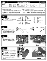
step 1
ADD MOUNTS TO THE SERVO
Find the appropriate #9180 servo horn for your servo from the chart at
right. Install the #3858 ball end into the servo horn. Add the #6272 dust
cover. Remove the servo horn from your servo and replace it with the
#9180 horn that you selected, then fasten with the stock mounting
screw that came with your servo in the position shown below.
DO NOT
POINT IT STRAIGHT UP!
See drawing for correct dimension.
Find the appropriate #7336 offset spacer for your servo from the chart
at right. Attach the spacer, if any, in between the #7336 mount and the
servo with the #7337 washers and #6917 (6860*) screws.
9180
SERVO TYPE SPACER SERVO ARM
Airtronics
94102 no spacer
A
Airtronics
94155, 94156, 94157, 94158, 94257,
thick spacer
A
94258, 94737, 94738, 94741, 94452
Futaba
S3003, S9404, S9402, S9303, S3401, no spacer
F
S9101, S9202
Hitec
S-300, HS-303, HS-525BB, HS-545BB, no spacer
H
HS-422, HS-425, HS-605BB,
HS-615MG, HS-925MG, HS-945MG
JR
Z8450, Z8550,
NES-4721, NES-4735, Z4750 no spacer
J
JR
Z250, Z550, Z2750
thin spacer
J
KO
PS-1012 FET, PS-2000 FET, no spacer
J
PS-2001 FET, PS-2004 FET,
PS-2015 FET
On Futaba servo S3003 and on all KO servos you will need to trim a
little off the sides of the servo ears. We have not tested any servos that
were released after mid-1999.
3858
6272
7336
offset spacer
7336
servo mount
7337
6917,
6860*
7337
step 2
MOUNT THE SERVO
Mount the servo to the chassis with two #7673
(6934*) screws.
Twist #6274 ball cups onto #1356 blue turnbuckle or
#3867 steel turnbuckle until you get the dimension
shown.
Use needle-nose pliers to attach the link
to the ball ends.
7673,
6934*
1.56 in
6274
1356 or 3867
step 3
INSTALL YOUR MOTOR
Attach the #3930 (3932*) motor
cam to the optional motor with two
#3934 button head motor screws.
Install the optional pinion gear of your
choice. (Refer to the gearing chart on
page 19.)
Install the two #4449 locknuts to the
underside of the chassis. These fit tight,
so be sure to put them in straight and
all the way in.
Slide the motor and cam down into the
groove of the chassis.
3930, 3932*
3934
3934
4449
4449
3931,
3933*
6928
3929
6274
39.6 mm
trim edges
so servo
will fit
trim edges
so servo
will fit
Motor not included in kit.
Pinion gear not included in kit.
1/16" (1.5mm)
See page 19, Radio Adjustments,
for more info on correctly
setting steering linkage.
See page 19,
Radio Adjustments,
for more info on correctly
setting steering linkage.
3929
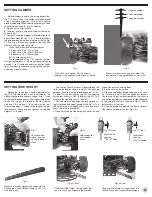
Screw down the #6928 inner
screw first until the #3931
(3932*) motor clamp just
touches the chassis bulkhead.
Set your gear mesh.
Slide the #3929 spring onto the
#3929 screw and thread in only
until there is no free play
between
the screw and spring. Now tighten
the screw 2 to 3 turns.
No more.
It is
normal to have an approximately
.040"-.050" (1 to 1.2mm) gap remain
between the clamp and the
bulkhead, as shown.
6
Small gap,
.040-.050"
(1-1.2mm)
No gap
About .220"-.250" (5.5-6.5mm)
when correctly tightened
6917,
6860*
6917,
6860*
6917,
6860*


