


1° negative camber
2° (recommended)
3° negative camber
25
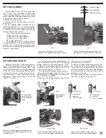
SETTING CAMBER
Setting camber is one of the tuning options that
the TC3 offers. To set the camber we recommend
using a camber gauge, 3x5” card or just a square
piece of cardboard. When adjusting camber you need
to have the car ready to run with no body.
1.
Set the car on a flat surface.
2.
Take your 3x5 card and push it against the tire as
shown in fig. 1.
3.
Use your supplied molded turnbuckle wrench to
adjust the camber link to 1°, 2° or 3° by either eyeball
the gap between the card and the top of the tire (fig.
2), or place a ruler across the top of the tires and
measure from the card to the tire.
(If you really want to know exact figures,
1° produces a .045” (1.1mm) gap,
2° produces a .088” (2.2mm) gap, and
3° produces a .130” (3.3mm) gap.
But it’s hard to measure!)
We recommend using 2° of negative camber.
On high traction tracks 2° to 3° negative camber would
be used, 1° to 2° would be used in low traction condi-
tions. We don’t recommend using positive camber
under any circumstances.
Fig. 1
Push a 3x5 card against the tire. Arrow is
pointing to the negative camber gap at the top.
Fig. 2
Eyeball or measure the gap for camber. We
recommend 2° negative camber to start with.
SETTING RIDE HEIGHT
Setting the ride height is another adjustment of
the TC3. The ride height is easily adjusted by the
#8846 shock preload spacers, shown in fig. 1, used
for the non-threaded shocks. The suggested preload
for the TC3 is one 1/8” preload for the front shocks
and one 1/8” and one 1/16” spacers for the rear
shocks. (See page 17, step 6 for more about the pre-
load spacers.) These preload spacers set the ride
height at ¼” (6.0mm).
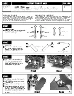
The Factory Team Kit shocks are adjusted by the
collar on the bodies, shown in fig. 2A. The spacing
between the collars on the threaded shocks is 7/64”
(2.78mm) for the front shocks (fig. 2B). The spacing
for the rear shocks is 9/64” (3.58mm) (fig. 2C). This
also sets the ride height at ¼” (6.0mm).
For adjusting the ride height we recommend us-
ing Associated ride height gauge #1450 (fig. 3). The
ride height gauge is stepped every ½mm and every
every 1mm step is numbered.
1.
When adjusting the ride height you need to have
Fig. 1
Shock pre-load
spacer inserted
on non-threaded
shock.
Fig. 2B, front
Front shock
spacing:
7/64” (2.78mm)
Fig. 2C, rear
Rear shock
spacing:
9/64” (3.58mm)
Fig. 2A
Adjusting collar
on threaded
shock.
Fig. 3
Measure your ride height quickly and easily with
Associated’s Ride Height Gauge #1450 (not
included in kits).
the car ready to run with no body.
2.
Set the car on a flat surface.
3.
Slide the ride height gauge underneath the chas-
sis, as shown in fig. 4A, until the gauge just touches
the chassis. To get a measurement on the chassis
and not the bumper, you might need to slide the gauge
in the corner of the car as shown in fig. 4A. Check
both corners of the front.
4.
Slide the gauge underneath the back of the car.
Check both corners of the rear (fig. 4B).
Fig. 4A, front
Slide your Ride Height Gauge under the
chassis so you don’t measure the bumper.
Fig. 4B, rear
Slide your Ride Height Gauge under the
chassis so you don’t measure the bumper.


