6
B A G B
REMOVE THESE
PARTS FOR:
TEAM: steps 4-6
1:1
T O O L S U S E D
4449, qty 5
4-40 locknut
1:1
4442, qty 2
dampener brace
standoff
1:1
6919, qty 5
4-40 x 5/16
1:1
6917, qty 3
4-40 x 3/8
8818, qty 2
rear body mount
4557, qty 1
rear chassis brace
1:1
4441, qty 1
dampener center post
1/16"
1:1
4448, qty 5
4-40 ball end
blue aluminum
1:1
7673, qty 2
4-40 x 5/16
4556, qty 1
dampener plate
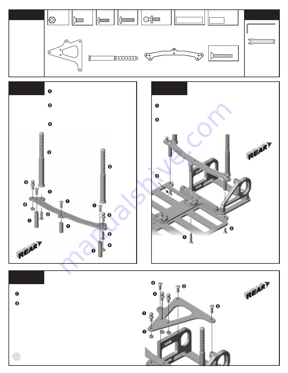
T-BAR MOUNTING
Insert the #6915 screw up through the chassis and
into the rear part of the T-bar, and screw it into the
center chassis brace standoff tube.
Secure the outside aluminum standoffs to the
chassis with the #7673 screws.
s t e p 5
L E F T S I D E
REAR CHASSIS BRACE ASSEMBLY
Mount the aluminum #4442 and #4441
standoffs to the #4557 rear chassis brace
with the #6919 screws.
Mount the #8818 rear body mounts to the
rear chassis brace in the holes shown and
secure the mounts using the #6917
screws.
Mount the #4448 aluminum ball ends to
the rear chassis brace with the #4449
locknuts.
s t e p 4
L E F T S I D E
DAMPENER PLATE ASSEMBLY
Install the three #4448 ball ends and three #4449 locknuts
where shown.
Install the #4556 dampener plate to the rear pod using two
#6919 screws into the aluminum bulkhead and the longer
#6917 screw into the plastic bulkhead.
s t e p 6
L E F T S I D E
6919
6919
4442
4442
4441
6917
6917
4448
4449
4449
6915
7673
7673
4449
4448
4448
6919
6919
6917
4556
8818
8818
4557
4448
1:1
6915, qty 1
4-40 x 5/8
6919


