PN#
500-10550
Page 5
Rev. D, 12/14
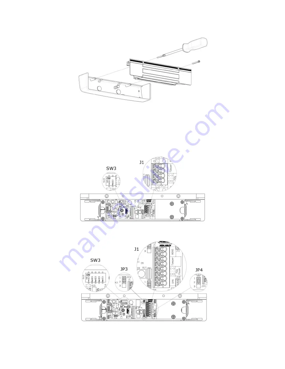
Figure 1. Removing the Cover Screws
Locating and Setting the Components in the M670 and M680BD
1. LOCATE and SET the components in the M670 and M680BD using Figure 2, “M670
SW3 and J1 Locations,” Figure 3, “M680BD SW3, JP3, JP4, and J1 Locations,” and
Table 1, “Component Label, Name, Selection, and Position.”
Figure 2. M670 SW3 and J1 Locations
Figure 3. M680BD SW3, JP3, JP4, and J1 Locations


