42
EN
Configurations
DIP switch
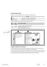
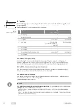
DIP switches (Fig. 4) are used to configure the IO module’s connection to the
Hi-O Technology™
bus and
the Hi-O devices.
All DIP switches are in the Off position (Tab. 2) by default.
DIP
Function
off
factory setting
on
1
Hi-O group
0
1
2
Terminating resistor
–
120 Ω
3
Plug & Play
switched on
switched off
4
Lock type
Coupling lock
(or lock with monitoring
function)
Motorised lock
5
No function
–
–
6
No function
–
–
7
Monitoring of the fire alarm system
switched off
switched on
8
No function
–
–
DIP switch 1 – Hi-O group setting
Hi-O Technology™
devices can be divided into two groups (“Organise products in Hi-O groups”,
page 39). Only the devices of a Hi-O group can exchange messages and control commands amongst
one another. The messages and control commands of the respective other Hi-O group are ignored.
DIP switch 2 – Activate terminating resistor (terminate)
The
Hi-O Technology™ bus
must be terminated with a terminating resistor. As the default setting, the
terminating resistor is activated at the lock but not at the IO module.
DIP switch 3 – Disable Plug & Play
The devices at the
Hi-O Technology™-Bus
are switched on when the power supply is switched on. First,
automatic device detection will run –
Plug & Play
(“Status messages / LEDs”, page 39).
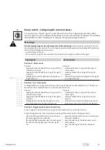
Note!
DIP switch 3 must always be switched in ongoing operation:
The automatic recognition must be com-
pletely finished before DIP switch 3 is set to
On
.
· If a Hi-O device is removed, added or exchanged, set DIP switch 3 to
Off
during ongoing operation
beforehand.
If this is not done, the device (lock) cannot be used in a different
Hi-O Technology™ bus
or separate indi-
vidual device (standalone device).
8 7 6 5 4 3 2 1
on
off
S2
Factory setting
Tab. 2 :
DIP switch functions
I
Summary of Contents for Hi-O Technology OneSystem N5950
Page 29: ...29 DE...
Page 57: ...57 Problem cause solution EN...
Page 85: ...85 FR...
Page 86: ...86 FR...
Page 87: ...87 FR...


