31
EN
Product information . . . . . . . . . . . . . . 32
The OneSystem
®
IO module N59504 . . 32
The OneSystem
®
IO module N5950
offers . 32
The Hi-O Technology™ bus . . . . . . . . . . . . 32
The Hi-O Technology™ bus offers . . . . . . . . . . 32
Notices . . . . . . . . . . . . . . . . . . . . . . . . . . . 33
About these instructions . . . . . . . . . . . . . . 33
Meaning of symbols . . . . . . . . . . . . . . . . . . . 33
Safety instructions . . . . . . . . . . . . . . . . . . . . 34
Intended use . . . . . . . . . . . . . . . . . . . . . . . . . . 35
Inputs and outputs . . . . . . . . . . . . . . . . 36
Assignment of inputs and outputs . . . . . 36
Inputs. . . . . . . . . . . . . . . . . . . . . . . . . . . . . . . . . 37
Input
E1
– External release . . . . . . . . . . . . . . . . . 37
Input
E2
– External door contact . . . . . . . . . . . 37
Input
E3
– Central locking. . . . . . . . . . . . . . . . . . 37
Input
B
– Fire alarm system. . . . . . . . . . . . . . . . 37
Outputs / relays . . . . . . . . . . . . . . . . . . . . . . . 38
Relay
R1
– Outer door handle . . . . . . . . . . . . . . 38
Relay
R1
– Fire alarm system . . . . . . . . . . . . . . . 38
Relay
R2
– Inner door handle actuated . . . . . 38
Relay
R3
– Locking cylinder actuated . . . . . . . 38
Relay
R4
– Door handle coupling . . . . . . . . . . . 38
Relay
R4
– Swing door drive . . . . . . . . . . . . . . . . 38
Relay
R5
– Unlocked . . . . . . . . . . . . . . . . . . . . . . . 38
Relay
R6
– Unlocked . . . . . . . . . . . . . . . . . . . . . . . 38
Relay
R7
– Door closed . . . . . . . . . . . . . . . . . . . . 38
Relay
R8
– Alarm / fault. . . . . . . . . . . . . . . . . . . . . 38
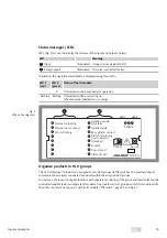
Status messages / LEDs. . . . . . . . . . . . . . . . . 39
Organise products in Hi-O groups . . . . . 39
Configurations . . . . . . . . . . . . . . . . . . . . 40
Open housing
. . . . . . . . . . . . . . . . . . . . . . . . . . . . . 40
Circuit board . . . . . . . . . . . . . . . . . . . . . . . . . . 40
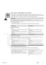
Rotary switch – Configuring the
external release . . . . . . . . . . . . . . . . . . . . . . . 41
Position 0 – Direct mode . . . . . . . . . . . . . . . . . . . 41
Positions 1 to E – Time mode . . . . . . . . . . . . . . . 41
Position F – Toggle mode for permanent
release. . . . . . . . . . . . . . . . . . . . . . . . . . . . . . . . . . . . . 41
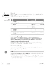
DIP switch. . . . . . . . . . . . . . . . . . . . . . . . . . . . . 42
DIP switch 1 – Hi-O group setting . . . . . . . . . . 42
DIP switch 2 – Activate terminating
resistor (terminate) . . . . . . . . . 42
DIP switch 3 – Disable Plug & Play. . . . . . . . . . . 42
DIP switch 4 – Lock type. . . . . . . . . . . . . . . . . . . . 43
DIP switch 5 – no function. . . . . . . . . . . . . . . . . . 43
DIP switch 6 – no function. . . . . . . . . . . . . . . . . . 43
DIP switch 7 – Monitoring of the
fire alarm system . . . . . . . . . . . . 43
Jumper . . . . . . . . . . . . . . . . . . . . . . . . . . . . . . . . 43
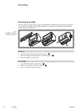
Mounting. . . . . . . . . . . . . . . . . . . . . . . . . 44
Mounting / disassembly . . . . . . . . . . . . . . . 44
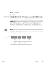
Electrical connection . . . . . . . . . . . . . . . . . . 45
Power supply . . . . . . . . . . . . . . . . . . . . . . . . . . . . . . 45
Identification of the cable . . . . . . . . . . . . . . . . . . 45
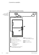
Connection examples . . . . . . . . . . . . . 46
Single-leaf panic door with monitoring 46
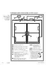
Double-leaf panic door with
monitoring – one Hi-O group . . . . . . . . . . 47
Double-leaf panic door with
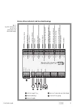
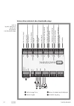
monitoring – two Hi-O groups . . . . . . . . . 48
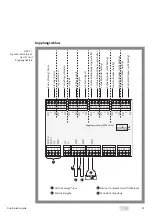
Motorised lock in operation with
fire alarm system . . . . . . . . . . . . . . . . . . . . . . 49
Motorised lock in operation without
fire alarm system . . . . . . . . . . . . . . . . . . . . . . 50
Coupling lock . . . . . . . . . . . . . . . . . . . . . . . . . 51
Connect fire protection module . . . . . . . 52
Technical specifications. . . . . . . . . . . . 53
Accessories, maintenance,
warranty, disposal . . . . . . . . . . . . . . . . 54
Accessories . . . . . . . . . . . . . . . . . . . . . . . . . . . 54
Warranty . . . . . . . . . . . . . . . . . . . . . . . . . . . . . . 54
Disposal. . . . . . . . . . . . . . . . . . . . . . . . . . . . . . . 54
Problem, cause, solution . . . . . . . . . . 55
No reaction to control signal . . . . . . . . . . 55
LED on relay 8 is not lit. . . . . . . . . . . . . . . . . 56
Updated information. . . . . . . . . . . . . . . . . . 56
Contents
Summary of Contents for Hi-O Technology OneSystem N5950
Page 29: ...29 DE...
Page 57: ...57 Problem cause solution EN...
Page 85: ...85 FR...
Page 86: ...86 FR...
Page 87: ...87 FR...


