47
EN
EN
Configuration
Setting options on the escape door control terminal
Fig. 5 :
Switching elements
and connections
1 2 3 4 5
JP1
JP2
S4
S3
S2
S1
F2
F1
Jumpers (Tab. 1)
DIP switch S4 (Tab. 2)
ON
OFF
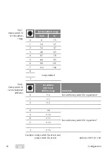
Rotary switch S1 (Tab. 3)
Rotary switch S3 (Tab. 5)
A B C D E
Rotary switch S2 (Tab. 4)
Arrangement diagram
Jumpers
Function
JP1
plugged
in at
factory
Pre-alarm switched on: An acoustic pre-alarm is triggered
before an alarm. The pre-alarm does not affect the alarm
contact or the visual display.
open
Pre-alarm switched off: An acoustic pre-alarm is suppressed.
After the time set on rotary switch S2 has elapsed, the alarm
is triggered.
JP2
plugged in
at factory
Permanent release switched on: Permanent release via the
key switch of the escape door control unit is possible.
open
Permanent release switched off: Permanent release via the
key pushbutton is not possible.
Tab. 1
JP-1 and JP-2
(Fig. 5)
Summary of Contents for EffEff 1338-14
Page 31: ...31 DE Checkliste Pr fung vor der Erstinbetriebnahme...
Page 63: ...63 EN EN Check list Testing before initial operation...
Page 66: ...66 EN...
Page 67: ...67 EN EN...


