SE LP10 ML20600 Mortise Lock
9
Copyright © 2020, ASSA ABLOY Access and Egress Hardware Group, Inc. All
rights reserved. Reproduction in whole or in part without the express written
permission of ASSA ABLOY Access and Egress Hardware Group, Inc. is prohibited.
6) Wiring Diagrams (Continued)
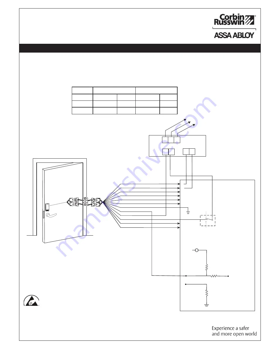
Typical (UL294-Compliant) SE LP10 Mortise Application Diagram #1
Tamper will trigger when reader is removed from door and tamper wiring is connected at the panel.
SE LP10
12 Conductor
ElectroLynx Harness
From McKinney
READER NEG - Black, 1
READER POS - Red, 2
DATA 1 - White, 3
DATA 0 - Green, 4
RX (NO) - Orange, 5
RX (COM) - Blue, 6
*EARTH GROUND - Brown, 7
TAMPER - Yellow, 8
LOCK NEG - Violet, 9
LOCK POS - Gray, 10
DPS (NC) - Pink, 11
DPS (COM) - Tan, 12
(-)
12VDC
(+)
DATA 1
DATA 0
RX (NO)
RX (COM)
Electrical
Access
Control
Panel
(By Others)
Use (NC) for
Fail Safe
Operation
Lock Relay
(NO) Fail
Secure
Operation
DPS
DPS
QC12 Electric
Hinge From
McKinney
Panel Circuitry
Unsupervised Open
Collector Tamper
5VDC
A to D Converter
1K
Ω
1K
Ω
1K
Ω
Input
Connection (+)
Input
Connection (
-
)
*IMPORTANT: Pin 7 must be tied to earth ground in the access
control panel.
Wiring in accordance with the NEC, ANSI/NFPA 70
Fail secure installations are subject to approval of local AHJ
Fail secure installations shall permit use of Listed panic
hardware to allow emergancy exit from the protected area.
Failure to follow proper ESD safe grounding procedures could
lead to equipment failure.
*UL294 is a United States based standard.
12V
24V
Average
Peak
Average
Peak
Reader
100mA
220mA
n/a
n/a
Actuator
15mA
500mA
15mA
500mA
12/24VDC System
Power Supply
(By Others)
12-24VDC
H N G
120 VAC
Input
Black (Hot)
White (Neutral)
Gr
een (Gnd)
12VDC
- +
- +


