background image

ED5800 (A) Series

Installation Instructions

Concealed Vertical Rod Exit Devices

FM171 01/19

Copyright © 2012, 2019, ASSA ABLOY Access and Egress Hardware Group, Inc. All rights reserved. Reproduction in whole 
or in part without the express written permission of ASSA ABLOY Access and Egress Hardware Group, Inc. is prohibited.

For installation assistance contact Corbin Russwin 
1-800-543-3658 • [email protected]

5

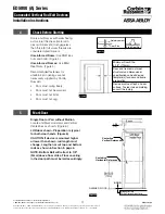
Hinge edge

of door

Verify there is no

gap between end

cover & touch bar

prior to marking

cutoff.

Mark cutoff line.

Cut square on line.

2-1/4

(57)

Minimum: 1-3/8

(35)

Minimum to inside edge of Hinge Stile: 3/8

(10)

Centerline
Dogging
Hole

CL

Align mounting holes in door

with mounting holes in device.

Align horizontal line on door

with edge of device.

LHR Door Open

Inside Face

6

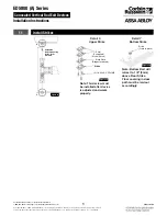
Prepare Door, Frame and Sill

A. Locate Device Template aligning 

VERTICAL REFERENCE and 
HORIZONTAL REFERENCE lines on 
door and template. Tape template to 
door face. (Figure 7)

B. Locate Top Strike and Bottom Strike 

templates, aligned on centerline 
of Rods and Strikes on door. Tape 
templates in place and mark holes. 
(Figure 7)

C. Locate and tape Trim template to door. 

(See instructions packed with trim.)

D. Mark and prepare holes per installation 

template.

Device and Bolt Case Plates: 

Each two (2) 1/4-20 machine screws for metal 
reinforced doors OR  
two (2) 3/8" (10) dia. sex nuts and bolts 

Top Strike:  

Two (2) 10-24 machine screws  

NOTE: Third screw MUST ONLY be used  
to lock strike in final position (Step 8C).
Bottom Strike: 

5/8" (16) dia. x 3/4" (19) deep 

hole

7

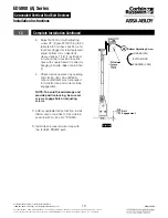
Size Device

Device must be 
field cut to size, 
unless standard 
opening and device 
are 36" (0.91m). 
(Figure 8)

Figure 7 

Top Strike Template

(Mounts on Frame Rabbet)

Device  Paper

Template

Floor Strike Template

(Mounts on Finished Floor)

FINISHED FLOOR

LHR DOOR

INSIDE FACE

CENTERLINE

VERTICAL

REFERENCE

CENTERLINE
HORIZONTAL
REFERENCE

Centerline

Rods & Strikes

Figure 8 

Summary of Contents for Corbin Russwin ED5800 Series

Page 1: ...re of fire labeled devices To Dog Device 1 Insert dogging key 2 Hold touchbar depressed 3 Turn key 1 4 turn clockwise Cover 2 1 4 20 X 3 4 PRHMS Special Head 2 8 32 X 2 PHPMS Temporary Screws 2 E Ring...

Page 2: ...d Egress Hardware Group Inc is prohibited For installation assistance contact Corbin Russwin 1 800 543 3658 techsupport corbinrusswin assaabloy com 2 To Change Hands 3 Maintenance 3 Options 3 Check Be...

Page 3: ...otate device to opposite orientation 180 degrees 3 Insert Lifter Assembly and reinstall screws NOTE Lifter must fit under lift block as shown Figure 1 Figure 1 Figure 2 3 Options 1 4 20 Sex Nut Option...

Page 4: ...reely Door must not be warped Door must not bind Door must not sag Figure 4 Figure 5 Reinforcement Door Skin Blind Rivet Nut 5 Mark Door Single Door or Pair without Mullion Locate and Mark Horizontal...

Page 5: ...mplate aligning VERTICAL REFERENCE and HORIZONTAL REFERENCE lines on door and template Tape template to door face Figure 7 B Locate Top Strike and Bottom Strike templates aligned on centerline of Rods...

Page 6: ...ail 3 Figure 11 F Set top latch assembly in place on door Maintain 7 8 22mm location from top of door as shown Figure 13 G Align yoke pin holes in arm and bracket assembly with alignment hole in rod s...

Page 7: ...yoke pin assemblies into arm and bracket assemblies Detail 1 A C E B Figure 15 8 32 PHPMS Temporary Screw 1 4 6 4 Yoke Pin Set Screw E ring Groove 10 Install Device A Mount trim when required Follow i...

Page 8: ...stance contact Corbin Russwin 1 800 543 3658 techsupport corbinrusswin assaabloy com 8 X Y Centerline Device Mounting Holes Rods Strikes Shim 2 supplied Start with one Strike Plate Ridges face down St...

Page 9: ...door Bolts extend automatically and should deadlock when door closes and top strike hits tripping lever Top bolt should retract flat Bottom bolt should travel 1 2 13 and engage 3 8 9 5 into strike in...

Page 10: ...ntinued Figure 22 3 Adjust bottom rod with adjusting screw C2 Figure 22 With top latch retracted in hold back position and touchbar dogged or fully depressed adjust bottom rod so deadbolt clears strik...

Page 11: ...1 All ED5000 Series Devices Rim and SecureBolt Against Frame Stop or Mullion when applicable For Rim and SecureBolt Exit Devices Only Vertical Reference Trim Only Against Door Surface Trim Only Horizo...

Page 12: ...dware Group Inc All rights reserved Reproduction in whole or in part without the express written permission of ASSA ABLOY Access and Egress Hardware Group Inc is prohibited Corbin Russwin 225 Episcopa...

Reviews: