18
EN
Installation and connection
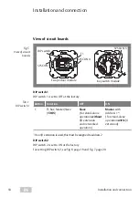
View of circuit boards
Fig. 5 :
View of circuit
boards
5 6 7
4
3
2
1
8
10 9
1211
16
15
14
13
6
4
3
2
1
5
3
2
1
12
DIP switch
SYSCON 4
SYSCON 5
SYSCON 5
Escape door module
Key switch module
F1
DIP switch 1
DIP switch 1 is set to OFF at the factory.
Button
Function
OFF
ON
1
TS bus: Master/Slave
(
1385
)
Slave
(For stand-alone
operation
without
I/O extension
and networked
operation)
Master
with
Address 1 *
)
(For stand-alone
operation
with
I/O
extension)
*)
If an I/O extension is used, this must be assigned to address
2
.
DIP switch 2
DIP switch 2 is set to ON at the factory.
For setting DIP switch 2, see Fig. 6 page 19 and Fig. 7 page 20.
Tab. 1 :
DIP switch 1
Installation and connection


