21
EN
Installation and connection
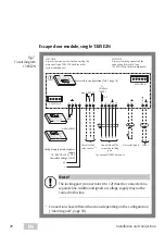
Key switch module 1385ES1
Fig. 8 :
Circuit diagram
1385ES1
SYSCON-5
1
1
2
2
3
3
4 5
L
R
SYSCON-5
1
1
2
2
3
3
4 5
L
R
1
3
2
1
3
2
1385EVL5
Tampering
Tamper
JP1
Tampering
Tamper
JP1
SYSCON-5
1
1
2
2
3
3
4 5
L
R
1385EVL5
Tampering
Tamper
JP1
1
3
2
A
A
A
Max.
24 V/100 mA
Max.
24 V/100 mA
Max.
24 V/100 mA
Individual
Parallel


