background image

9

99

99

1.3

1.3

1.3

1.3

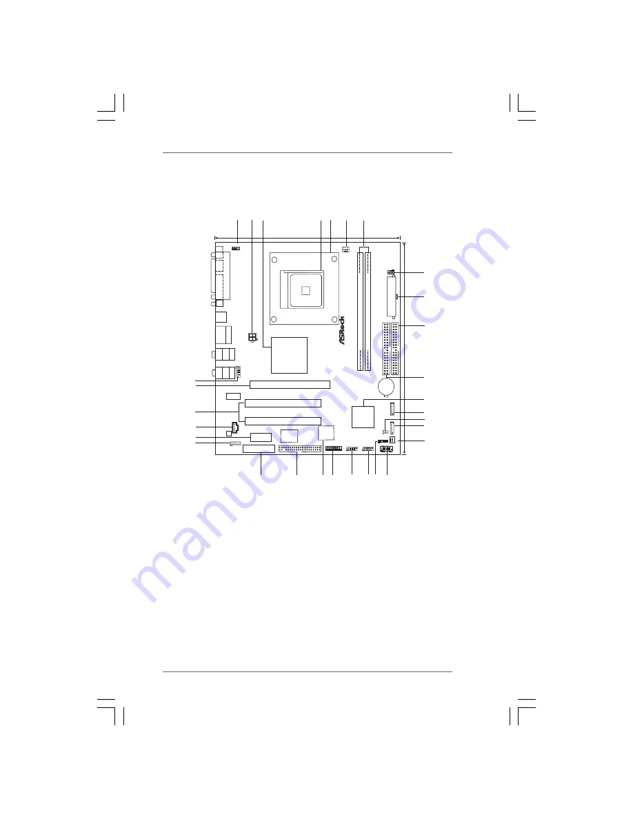
1.3 Motherboard Layout

Motherboard Layout

Motherboard Layout

Motherboard Layout

Motherboard Layout

Socket

754

ATX12V1

PS2_USB_PW1

1

P

A

RALLEL

P

ORT

VGA

PS2

Keyboard

PS2

Mouse

Top:
RJ-45

Top:

Line

In

To

p

:

REAR

SPK

USB 2.0
T: USB0
B: USB1

USB 2.0
T: USB2
B: USB3

Center:

Line

Out

Bottom:

Mic
In

Center:

SIDE

SPK

Bottom:

CTR

B

ASS

K8VM890

VIA

K8M890 CE

Chipset

VIA

VT8237A

21.3cm (8.4 in)

24.4cm

(9.6

in)

IDE1

IDE2

DDR

1

(64/72

b

it,

1

84-pin

module)

DDR2

(64/72

bit,

184-pin

module)

A

T

XPWR1

PCIE1

PCI2

PCI1

PCIE2

HDMR1

4Mb

BIOS

CD1

SA

T

A

1

SA

T

A

2

CPU_FAN1

PCI

EXPRESS

ATA133

DDR400

FSB800

SATA

7.1CH

HD

USB2.0

LAN
PHY

SUPER

I/O

COM1

RoHS

AUDIO
CODEC

HD_AUDIO1

1

CMOS

BATTERY

1

GAME1

1

SPEAKER1

PLED PWRBTN

1

PANEL 1

CHA_F

AN1

1

USB67

1

USB45

1

IR1

1

FLOPPY1

HDLED RST

CLRCMOS2

5

1

2 3

6

4

7

8

9

10

11

12

13

14

24

23

15

16

17

18

19

20

21

22

25

26

27

28

29

30

1

 1

PS2_USB_PW1  Jumper

16

Chassis  Fan  Connector  (CHA_FAN1)

 2

ATX  12V  Connector  (ATX12V1)

17

System  Panel  Header  (PANEL1)

 3

North Bridge  Controller

18

Chassis  Speaker  Header  (SPEAKER 1)

 4

754-Pin  CPU  Socket

19

USB 2.0  Header  (USB67, Blue)

 5

CPU  Heatsink  Retention  Module

20

USB 2.0  Header  (USB45, Blue)

 6

CPU  Fan  Connector  (CPU_FAN1)

21

Game  Port  Header  (GAME1)

 7

184-pin  DDR  DIMM  Slots  (DDR1- 2)

22

Flash  Memory

 8

Infrared  Module  Header  (IR1)

23

Floppy  Connector  (FLOPPY1)

 9

ATX  Power  Connector  (ATXPWR1)

24

HDMR  Slot  (HDMR1)

10

Primary  IDE  Connector  (IDE1, Blue)

25

Front  Panel  Audio  Header  (HD_AUDIO1)

11

Secondary  IDE  Connector  (IDE2, Black)

26

PCI  EXPRESS  Slot  (PCIE2)

12

South Bridge Controller

27

Internal  Audio  Connector: CD1 (Black)

13

Secondary  Serial  ATA  Connector  (SATA2)

28

PCI  Slots  (PCI1 - 2)

14

Clear  CMOS  Jumper  (CLRCMOS2)

29

PCI  EXPRESS  Slot  (PCIE1)

15

Primary  Serial  ATA  Connector  (SATA1)

30

COM  Port  Header  (COM1)

Summary of Contents for K8VM890

Page 1: ...1 1 1 1 1 K8VM890 User Manual Version 1 1 Published February 2006 Copyright 2006 ASRock INC All rights reserved...

Page 2: ...ASRock ASRock assumes no responsibility for any errors or omissions that may appear in this manual With respect to the contents of this manual ASRock does not provide warranty of any kind either expr...

Page 3: ...tion 19 2 9 Hot Plug and Hot Swap Functions for SATA HDDs 19 2 10 Installing Windows 2000 XP XP 64 bit With RAID Functions 20 2 11 Installing Windows 2000 XP XP 64 bit Without RAID Functions 21 2 12 U...

Page 4: ...Support CD Information 38 4 2 1 Running Support CD 38 4 2 2 Drivers Menu 38 4 2 3 Utilities Menu 38 4 2 4 Contact Information 38 APPENDIX AMD s Cool n Quiet APPENDIX AMD s Cool n Quiet APPENDIX AMD s...

Page 5: ...be updated the content of this manual will be subject to change without notice In case any modifications of this manual occur the updated version will be available on ASRock website without further no...

Page 6: ...DDR400 333 266 Max capacity 2GB Hybrid Booster CPU Frequency Stepless Control see CAUTION 3 ASRock U COP see CAUTION 4 Boot Failure Guard B F G Expansion Slot 2 x PCI slots 1 x PCI Express x 16 slot 1...

Page 7: ...nector 2 x USB 2 0 headers support 4 USB 2 0 ports see CAUTION 6 BIOS Feature 4Mb AMI BIOS AMI Legal BIOS Supports Plug and Play ACPI 1 1 Compliance Wake Up Events SMBIOS 2 3 1 Support Supports jumper...

Page 8: ...than the recommended CPU bus frequencies may cause the instability of the system or damage the CPU 4 While CPU overheat is detected the system will automatically shutdown Before you resume the system...

Page 9: ...RCMOS2 5 1 2 3 6 4 7 8 9 10 11 12 13 14 24 23 15 16 17 18 19 20 21 22 25 26 27 28 29 30 1 1 PS2_USB_PW1 Jumper 16 Chassis Fan Connector CHA_FAN1 2 ATX 12V Connector ATX12V1 17 System Panel Header PANE...

Page 10: ...t Connection Audio Output Channels Front Speaker Rear Speaker Central Bass Side Speaker No 7 No 4 No 5 No 3 2 V 4 V V 6 V V V 8 V V V V If you use 8 channel audio and enable Multi Streaming function S...

Page 11: ...ower is switched off or the power cord is detached from the power supply Failure to do so may cause severe damage to the motherboard peripherals and or components 1 Unplug the power cord from the wall...

Page 12: ...ed 2 2 2 2 2 2 2 2 2 2 Installation of CPU Fan and Heatsink Installation of CPU Fan and Heatsink Installation of CPU Fan and Heatsink Installation of CPU Fan and Heatsink Installation of CPU Fan and H...

Page 13: ...onnect power supply before adding or removing DIMMs or the system components Step 1 Unlock a DIMM slot by pressing the retaining clips outward Step 2 Align a DIMM on the slot such that the notch on th...

Page 14: ...of the expansion card and make necessary hardware settings for the card before you start the installation Step 2 Remove the system unit cover if your motherboard is already installed in a chassis Ste...

Page 15: ...dby current provided by power supply Clear CMOS CLRCMOS2 2 pin jumper see p 9 No 14 Note CLRCMOS2 allows you to clear the data in CMOS The data in CMOS includes system setup information such as system...

Page 16: ...ondary IDE Connector Black 39 pin IDE1 see p 9 No 10 39 pin IDE2 see p 9 No 11 Note If you use only one IDE device on this motherboard please set the IDE device as Master Please refer to the instructi...

Page 17: ...nnection and control of audio devices CD R GND GND CD L CD1 USB_PWR USB_PWR P 5 P 5 P 4 P 4 GND GND DUMMY 1 USB_PWR USB_PWR P 7 P 7 P 6 P 6 GND GND DUMMY 1 1 IRTX IRRX GND 5VSB DUMMY J_SENSE OUT2_L 1...

Page 18: ...connect the CPU fan 3 pin CPU_FAN1 cable to this connector and see p 9 No 6 match the black wire to the ground pin Game Connector Connect a Game cable to this 15 pin GAME1 connector if the Game port s...

Page 19: ...Plug and Hot Swap F 2 9 Hot Plug and Hot Swap F 2 9 Hot Plug and Hot Swap Functions for SA unctions for SA unctions for SA unctions for SA unctions for SAT T T T TA HDDs A HDDs A HDDs A HDDs A HDDs K...

Page 20: ...press Y E The system will start to format the floppy diskette and copy SATA drivers into the floppy diskette STEP 2 Use RAID Installation Guide to set RAID configuration Before you start to configure...

Page 21: ...TUP UTILITY Advanced screen IDE Configuration B Set the Onboard SATA Operation Mode option from RAID to non RAID STEP 2 Install Windows 2000 XP XP 64 bit OS on your system After setting up BIOS you ca...

Page 22: ...button on the system chassis You may also restart by turning the system off and then back on Because the BIOS software is constantly being updated the following BIOS setup screens and descriptions are...

Page 23: ...Screen When you enter the BIOS SETUP UTILITY the Main screen will appear and display the system overview System Time Hour Minute Second Use this item to specify the system time System Date Day Month...

Page 24: ...wrong values in this section may cause the system to malfunction BIOS SETUP UTILITY Main H W Monitor Boot Security Exit Advanced Settings WARNING Setting wrong values in below sections may cause syst...

Page 25: ...and Processor Voltage However it is recom mended to keep the default value for system stability BIOS SETUP UTILITY CPU Configuration Select how to set the CPU host frequency Select Screen Select Item...

Page 26: ...is Disabled It will allow better tolerance for memory compatibility when it is set to Enabled Bank Interleaving Interleaving allows memory accesses to be spread out over banks on the same node or accr...

Page 27: ...ault value is Auto TRP Use this to adjust TRP values Configuration options Auto 2CLK 3CLK 4CLK 5CLK and 6CLK The default value is Auto MA Timing Use this to adjust values for MA timing Configuration o...

Page 28: ...s accessing 8 bit ISA cards Disable this feature when using ISA cards that are not PCI 2 1 compliant OnBoard LAN This allows you to enable or disable the onboard LAN feature OnBoard HD Audio Select Au...

Page 29: ...Auto will enable this feature if the OS supports it If you set this item to Disabled the function Repost Video on STR Resume will be hidden Restore on AC Power Loss This allows you to set the power s...

Page 30: ...Primary IDE Master Primary IDE Slave Secondary IDE Master Secondary IDE Slave SATA1 SATA2 Enabled Hard Disk Not Detected Not Detected Not Detected Not Detected Not Detected Select Screen Select Item...

Page 31: ...Device such as MO LBA Large Mode Use this item to select the LBA Large mode for a hard disk 512 MB under DOS and Windows for Netware and UNIX user select Disabled to disable the LBA Large mode Block...

Page 32: ...uration Floppy Configuration In this section you may configure the type of your floppy drive BIOS SETUP UTILITY PCI PnP Configuration Value in units of PCI clocks for PCI device latency timer register...

Page 33: ...ault value is ECP EPP If this option is set to ECP EPP it will show the EPP version in the following item EPP Version Configuration options Normal Bi Directional and ECP EPP EPP Version Use this item...

Page 34: ...tem to enable or disable the USB 2 0 support Legacy USB Support Use this item to enable or disable the support to emulate legacy I O devices such as mouse keyboard etc Or you may select Auto so that t...

Page 35: ...priority BIOS SETUP UTILITY Hardware Health Event Monitoring Select Screen Select Item F1 General Help F9 Load Defaults F10 Save and Exit ESC Exit v02 54 C Copyright 1985 2003 American Megatrends Inc...

Page 36: ...ption F1 General Help F9 Load Defaults F10 Save and Exit ESC Exit v02 54 C Copyright 1985 2003 American Megatrends Inc Boot Boot From Network VIA SATA Raid Utility Bootup Num Lock Disabled Enabled On...

Page 37: ...creen Save Changes and Exit When you select this option it will pop out the following message Save configuration changes and exit setup Select OK to save the changes and exit the BIOS SETUP UTILITY Di...

Page 38: ...pport CD insert the CD into your CD ROM drive The CD automatically displays the Main Menu if AUTORUN is enabled in your computer If the Main Menu did not appear automatically locate and double click o...

Page 39: ...e to install AMD Processor Driver from the Support CD first If you are using Windows 2000 XP operating system please follow the instruction below to enable AMD s Cool n QuietTM technology 1 From the W...

Reviews: