6
Serie ATE
E N G L I S H
COMMISSIONING
Commission the fan and make sure that: 1) impeller rotation does not cause significant vibrations such to compromise the stability
of the impeller itself or of the electric motor; 2) the amperage values fall within the ones shown on the plate.
Should problems arise, immediately stop the fan and check the previously described operations again. In the first hours of
operation, check machine tightening and operation several times.
ADJUSTMENT
Should the fan be paired with a voltage/speed regulator, make sure that the capacity of the latter is appropriate for the current
absorbed by the fan motor.
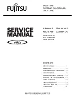
ELECTRICAL CONNECTIONS
wiring diagram to the external terminal board:
One speed three-phase connection
Single phase connection
4/6 – 6/8 pole double speed three-phase connection
INSTALLATION
The fan can be lifted by connecting the harness to the specific
eyebolts fitted on the dome.
Direct fastening to the support structure:
Secure the base of the fan (4) to the support structure (1, 1B) using screws and bolts (7) or
expansion plugs (3) with a diameter no greater than 10 mm.
WARNINg
: In no case can the fan be operated if it is installed on a support structure with
components removed.
LEgEND
1 Brick work
1B Iron
2 Damper packing
3 Expansion bolts
4 Fan base
5 water proff winding
6 welded hexagonal nut
7 Hexagonal head bolt